

Optical system having a diffractive optical element, and optical apparatus
a technology of optical elements and optical systems, applied in the field of optical systems having diffractive optical elements, can solve the problems of increasing difficulty, inability to achieve the effect of evenness of diffraction efficiency including the shading of a ray of light, and difficulty in obtaining excellent diffraction efficiency concurrently with both on-axial light flux and off-axial light flux
Inactive Publication Date: 2002-10-29
CANON KK
View PDF30 Cites 45 Cited by
- Summary
- Abstract
- Description
- Claims
- Application Information
AI Technical Summary
Benefits of technology
The advantageous effects mentioned in each of the first to third embodiments are effectively enjoyed by such an optical apparatus as disclosed in the present embodiment.
mentioned in each of the first to third embodiments are effectively enjoyed by such an optical apparatus as disclosed in the present embodiment.
Next, numerical data of the numerical examples 1 to 3 of optical systems corresponding to the first to third embodiments of the invention are shown.
In the numerical data of the numerical examples 1 to 3, f denotes the focal length, Fno denotes the F-number, .omega. denotes a half angle of view, ri denotes the radius of curvature of the i-th surface, when counted from the object side, di denotes the separation between the i-th surface and the (i+1)th surface, when counted from the object side, ni and .nu.i respectively denote the refractive index and Abbe number of the i-th optical member, when counted from the object side.
The shape of an aspheric surface is expressed in the coordinates with an X axis in the optical axis direction (the direction in which light advances) and an H axis in the direction perpendicular to the optical axis, with the intersection point between the aspheric surface and the X axis taken as the original point, by the following equation: ##EQU1##
where r is the radius of curvature of a paraxial portion of the aspheric surface, and A, B, C, D, E and F are aspheric coefficients.
Problems solved by technology
Accordingly, this construction has such a characteristic that, without the above state of passing-through of rays of light, it is impossible to obtain the effect of evenness of the diffraction efficiency including the shading of a ray of light.
Hei 10-268115 is applied to a photographic lens as it stands, it is difficult to obtain a diffraction efficiency excellent concurrently with respect to both the on-axial light flux and the off-axial light flux.
In particular, in the case of a photographic lens having a relatively large aperture, since the respective areas, on which an on-axial light flux and an off-axial light flux are made incident, of a lens surface having a diffraction grating provided thereon overlap each other greatly, the above-mentioned difficulty increases.
Method used
View moreImage
Smart ImageViewing Examples

Examples
numerical example 2
Numerical Example 3:
TABLE 1
With the above-described elements defined as set forth in each of the embodiments, it is possible to attain an optical system having such high optical performance that, when effecting achromatism by combining a diffractive optical element and a refractive optical element, the diffraction efficiency excellent over the entire image plane can be obtained even if light fluxes which are to reach respective positions of the image plane overlap each other greatly on a diffractive optical surface.
Login to View More PUM
 Abstract
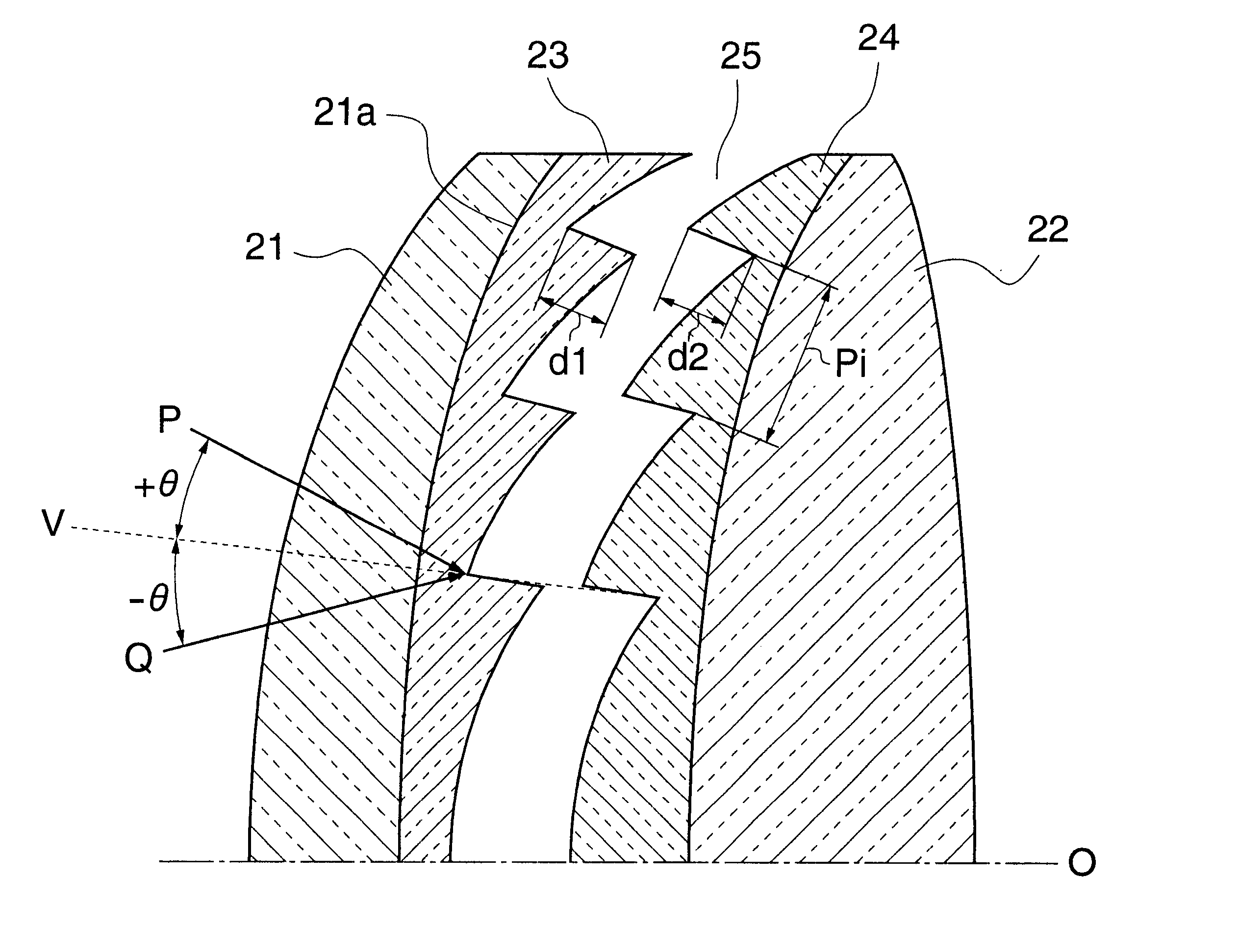
An optical system includes a diffractive optical element having a diffraction grating provided, on a lens surface having a curvature, in a concentric-circles shape rotationally-symmetrical with respect to an optical axis. The sign of the curvature of the lens surface having the diffraction grating provided thereon is the same as the sign of a focal length, at a design wavelength, of a system composed of, in the optical system, a surface disposed nearest to an object side to a surface disposed immediately before the lens surface having the diffraction grating provided thereon, and is different from the sign of the distance from the optical axis to a position where the center ray of an off-axial light flux enters the lens surface having the diffraction grating provided thereon. Further, the apex of an imaginary cone formed by extending a non-effective surface of the diffraction grating is located adjacent to the center of curvature of the lens surface having the diffraction grating provided thereon.
Description
1. Field of the InventionThe present invention relates to an optical system having a diffractive optical element, and more particularly to an optical system suited to optical apparatuses, such as film cameras, video cameras, digital cameras, telescopes, projectors, etc., in which a diffractive optical element and a refracting optical element are combined to effect achromatism well.2. Description of Related ArtHeretofore, as one of methods for correcting chromatic aberration of an optical system, there is a method of combining two glass materials (lenses) which differ in dispersion from each other.As against such a conventional method of combining two glass materials to diminish chromatic aberration, there is a method for diminishing chromatic aberration by providing, at a lens surface or a part of an optical system, a diffractive optical element, such as a diffraction grating, having a diffracting function, as disclosed in SPIE Vol. 1354 International Lens Design Conference (1990), ...
Claims
Login to View More Application Information
Patent Timeline
 Patent Type & AuthorityPatents(United States)
IPC IPC(8): G02B5/18
CPCG02B5/1895G02B27/4211
InventorOGAWA, HIDEKI
OwnerCANON KK