Opto-electric device for measuring the root-mean-square value of an alternating current voltage

a technology of alternating current and opto-electric devices, which is applied in the direction of measurement devices, effective value measurements, instruments, etc., can solve the problems of limited dynamic range of devices, less bandwidth, and limited device dynamic range,

Inactive Publication Date: 2002-11-12
SRICO
View PDF44 Cites 34 Cited by
  • Summary
  • Abstract
  • Description
  • Claims
  • Application Information

AI Technical Summary

Benefits of technology

will become apparent from the following disclosure in which one or more preferred embodiments of the invention are described in detail and illustrated in the accompanying drawings. It is contemplated that

Problems solved by technology

A wide-bandwidth multiplier (squarer) such as the AD834 allows input bandwidth from 5 Hz to over 20 MHz and a peak input of 10 V. The dynamic range of such devices is limited because the squarer must deal with a signal that varies enormously in amplitude.
Because of this effect, such devices are typically limited to a 10:1 dynamic range.
Although this increases the dynamic range of the circuit, it comes at the expense of less bandwidth.
Although the accuracy of the thermal voltage converter is superior to

Method used


Image

  • Opto-electric device for measuring the root-mean-square value of an alternating current voltage
  • Opto-electric device for measuring the root-mean-square value of an alternating current voltage
  • Opto-electric device for measuring the root-mean-square value of an alternating current voltage

Examples


Embodiment Construction

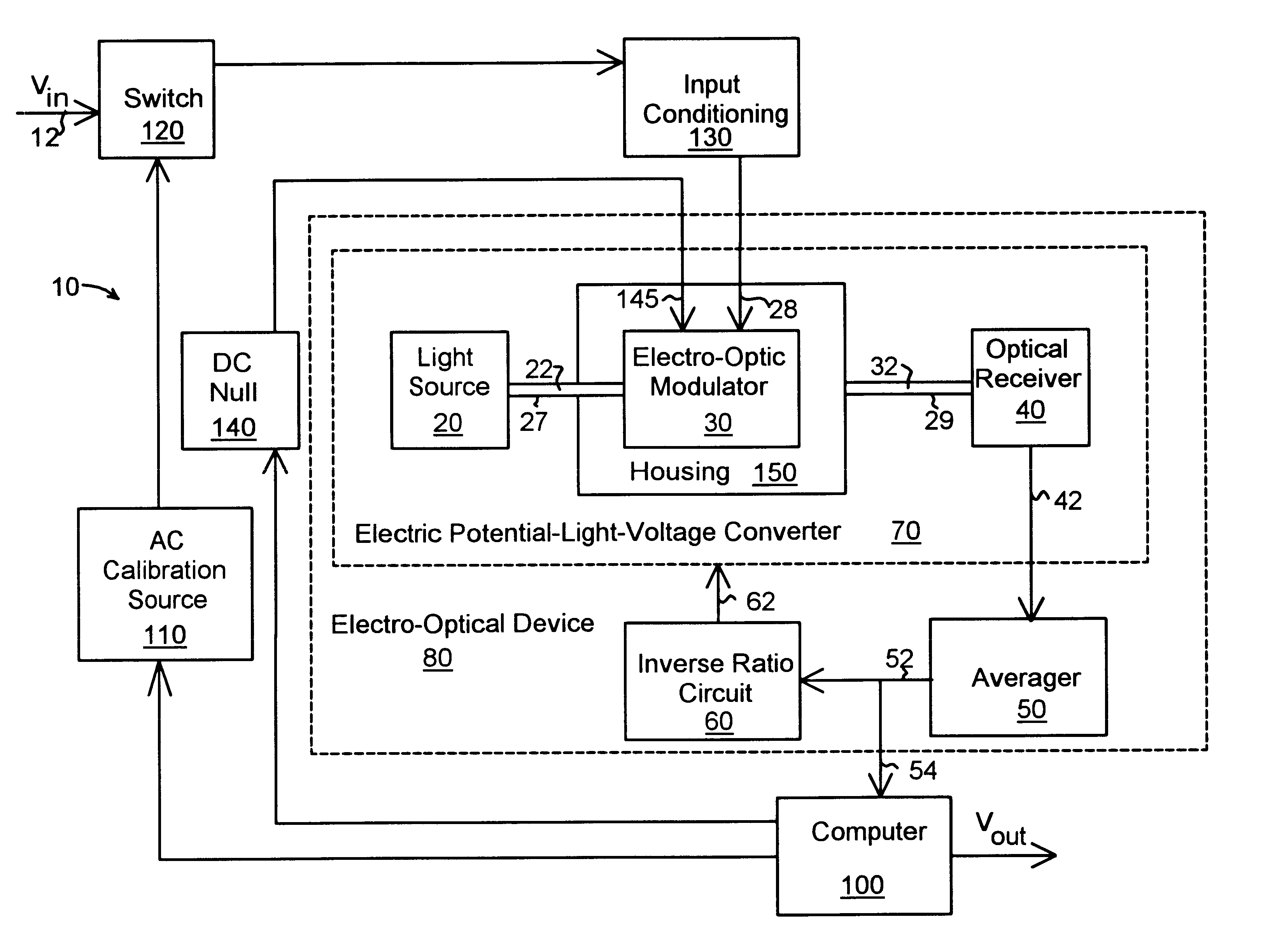
With reference to the drawings and initially FIG. 1, a measurement device 10 for measuring the true root-mean-square value of an alternating current comprises an electric field-light-voltage converter 70 with a light source 20, electro-optical device 30 for receiving and modulating light 22 from the light source 20 as a square law device under the influence of an electric field produced by an input voltage from line 28. The modulated light 32 is received by an optical receiver 40 to produce a first voltage that is proportional to the square of the input voltage in line 28. The first voltage passes to an averager 50 by means of connection 42 where averager 50 provides a second voltage that is proportional to the average of the square of the electric field over a period of time. The voltage output in line 52 is then feed to an inverse ratio circuit 60 that returns an inverse voltage of the voltage in line 52 to the electric potential-light-voltage converter 70 by means of line 62. By ...


PUM


Abstract

An opto-electric device for measuring the root mean square value of an alternating current voltage comprises: a) an electric field-to-light-to-voltage converter having 1) a light source; 2) an electro-optic material: (a) receiving light from the light source; (b) modulating said light; and (c) providing a modulated light output; 3) an electric field applied to the electro-optic crystal to modulate the light from the light source to produce the modulated light output; b) an optical receiver for receiving and converting the modulated output light from the electro-optic material to a first voltage that is proportional to a square of the electric field applied to the electro-optic material; c) an averager circuit receiving the first voltage and providing a second voltage that is proportional to the average of said square of said electric field over a period of time; and d) an inverse ratiometric circuit receiving the second voltage from the averager circuit and returning a third voltage that is an inverse voltage of the second voltage to the electric field-to-light-to-voltage converter to produce an output voltage that is the root mean square voltage of the applied electric field. The device uses a Mach_Zehnder interferometer operating a a square law device and features a housing for maintaining the interferometer at constant temperature using a temperature control unit. A nulling circuit is provided to maintain the interferometer at it null operating point as are calibration circuits to correct for voltage amplitude and frequency changes.

Description

1. Field of the InventionThis invention relates, in general, to an apparatus for measuring voltage and more particularly to apparatus for measuring the true root-mean-square (rms) voltage of an applied voltage signal.2. Background of the InventionTrue rms voltage electronic measurement devices are known and widely used. These devices electronically convert the AC voltage to a direct current (DC) output by squaring the voltage, averaging and then obtaining a square root. Integrated circuits (ICs) such as the AD536 from Analog Devices, Norwood, Mass. have less than 1% error at frequencies up to about 140 kHz with a 7 V rms input and 6 kHz at a 10 mV rms input. A wide-bandwidth multiplier (squarer) such as the AD834 allows input bandwidth from 5 Hz to over 20 MHz and a peak input of 10 V. The dynamic range of such devices is limited because the squarer must deal with a signal that varies enormously in amplitude. For example, an input signal of 1 mV to 100 mV results in a 1 mV to 10,000...

Claims


Application Information

Patent Timeline
IPC IPC(8): G01R15/24G01R19/02
CPCG01R15/241G01R19/02
Inventor KINGSLEY, STUART A.SRIRAM, SRIRAM S.KLEEFSTRA, MEINDERT
Owner SRICO
Why Eureka
Try Eureka