Method of calibrating an apparatus for producing a three-dimensional object, calibration apparatus and method and apparatus for producing a three-dimensional object

a three-dimensional object and calibration method technology, applied in numerical control, pretreatment surfaces, lamination, etc., can solve the problems of inability to absolutely calibrate the control, difficult compatibility with following processes, and exact position of light-sensitive mediums

Inactive Publication Date: 2002-11-19
EOS ELECTRO OPTICAL SYST
View PDF16 Cites 176 Cited by
  • Summary
  • Abstract
  • Description
  • Claims
  • Application Information

AI Technical Summary

Benefits of technology

It is an object of the invention to provide an improved method of calibrating an apparatus for producing a three-dimensional object. It is a further object of the invention to provide an improved apparatus for calib

Problems solved by technology

However, it is not possible to absolutely calibrate the control, because, in this method, the exact position of the light-sensitive medium in the rapid prototyping system is unknown.
This is a particular disadvantage, if the rapid prototyping system is used to form an object on a presintered plate and the finished object is remov

Method used


Image

  • Method of calibrating an apparatus for producing a three-dimensional object, calibration apparatus and method and apparatus for producing a three-dimensional object
  • Method of calibrating an apparatus for producing a three-dimensional object, calibration apparatus and method and apparatus for producing a three-dimensional object
  • Method of calibrating an apparatus for producing a three-dimensional object, calibration apparatus and method and apparatus for producing a three-dimensional object

Examples


Embodiment Construction

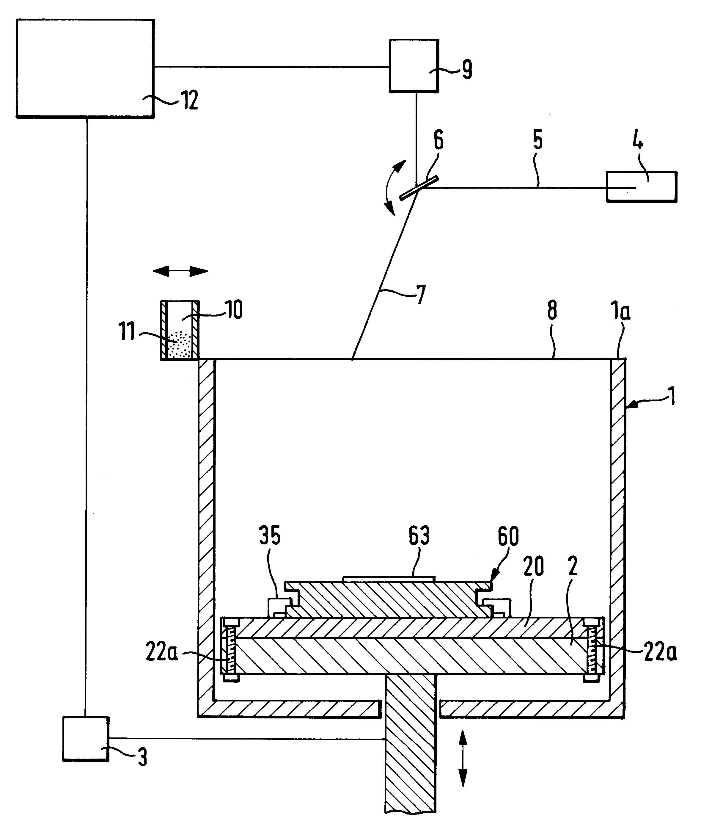
As shown in FIG. 1 a rapid prototyping system, being an apparatus for producing a three-dimensional object by layerwise solidification of a building material, comprises a container 1 having an open top, an object carrier provided within the container and having a base plate 2 which can be selectively lifted and lowered in vertical direction by means of a schematically indicated elevation adjustment device 3. The apparatus further comprises a radiation source 4 located above the container 1 and being formed as a laser issuing a focused laser beam 5. The laser beam 5 is deflected by a deflection apparatus 6, for example a rotating mirror, and focused as a deflected beam 7 onto a working plane 8 defined by the top edge la of the container. The radiation source 4 and the deflection apparatus 6 together form a radiation apparatus. A control device 9 controls the deflection apparatus 6 so as to direct the deflected beam 7 to any desired point in the working plane 8. Moreover, an applying ...


PUM

PropertyMeasurementUnit
Angleaaaaaaaaaa
Sensitivityaaaaaaaaaa

Abstract

The invention refers to a method for calibrating the control of a radiation device producing electromagnetic radiation or particle radiation in a rapid prototyping system. The method comprises the steps of arranging a calibration plate at a defined position in the rapid prototyping system, the calibration plate having an upper side with a first region and a second region separate from the first region, the first region being provided with optically detectable reference marks and the second region having a medium which is sensitive to the radiation of the radiation device, producing a test pattern by exposing said medium to said radiation at predetermined desired positions defined by position coordinate data, digitizing the first region of the calibration plate with the reference marks thereon and the second region of the calibration plate having the test pattern, comparing the digitized reference marks and the digitized test pattern and calculating and providing correction data for the control of the radiation device on the basis of the comparison.

Description

The invention relates to a method of calibrating an apparatus for producing a three-dimensional object, a calibration apparatus and a method as well as an apparatus for producing a three-dimensional object.Document EP 0 792 481 B1 discloses an apparatus for producing a three-dimensional object and a method of calibrating the control for deflecting a laser beam for rapid prototyping systems. According to this method a test pattern is generated by exposing a light-sensitive material to a laser beam at predetermined desired positions on the basis of position coordinate data. Portions of this test pattern are ditigized and the portions are combined to form an overall pattern. Correction data for the control can be calculated and provided by comparing the actual positions of the laser beam on the overall pattern with the position coordinate data. However, it is not possible to absolutely calibrate the control, because, in this method, the exact position of the light-sensitive medium in t...

Claims


Application Information

Patent Timeline
IPC IPC(8): B29C67/00G05B19/401B23K26/00B23K26/10G05B19/18
CPCB29C67/0088G05B19/4015G05B2219/37067G05B2219/37068G05B2219/37555G05B2219/37572G05B2219/49007B33Y50/00B29C64/386B29C64/393
Inventor PHILIPPI, JOCHENLOHNER, ANDREAS
Owner EOS ELECTRO OPTICAL SYST
Why Eureka
Try Eureka