Apparatus and method for sharing an external memory between multiple network switches

a network switch and external memory technology, applied in the field of networks, can solve the problems of limited external memory interface bandwidth, blockage behavior, and reduced bandwidth allocated to the remaining network switch ports

Inactive Publication Date: 2002-11-19
GLOBALFOUNDRIES INC
View PDF11 Cites 18 Cited by
  • Summary
  • Abstract
  • Description
  • Claims
  • Application Information

AI Technical Summary

Benefits of technology

This and other needs are attained by the present invention, where two or more network switches are arranged to access a single external memory through their respective external memory interfaces, thereby eliminating the need to transfer data frames over the expansion ports of the network switches within the arrangement. Further, the exchange of frame pointers between network switches utilizing the expansion ports, affords two or more network switches the capability to access the shared external memory without significantly increasing the size of each switch and extensively modifying the switch design.

Problems solved by technology

A difficulty in designing a network switch to be "non-blocking" (i.e., preventing delay in transferring a data packet received at an input switch port), yet with finite memory bandwidth resources, is ensuring that all ports within each network switch have sufficient memory resources allocated from a respective external memory to prevent the delay of data transmission.
However, if two or more network switches are connected together in a cascade arrangement through expansion ports requiring bandwidth to create a larger switch (e.g., a 24-port switch using two 12-port network switches), bandwidth allocated to the remaining network switch ports becomes reduced and possible blocking behavior may occur if the high bandwidth uplink is retained.
A primary cause of this problem is the limited bandwidth of the external memory interface which must now service twice as many ports.
Hence, expandability is difficult when connecting two or more switches together while also maintaining a "non-blocking" arrangement, especially in network switches under heavy network traffic conditions.

Method used


Image

  • Apparatus and method for sharing an external memory between multiple network switches
  • Apparatus and method for sharing an external memory between multiple network switches
  • Apparatus and method for sharing an external memory between multiple network switches

Examples


Embodiment Construction

The present invention will be described with the example of a switch in a packet switched network, such as an Ethernet (IEEE 802.3) network. It will become apparent, however, that the present invention is also applicable to other packet switched systems, as described in detail below, as well as to other types of systems in general.

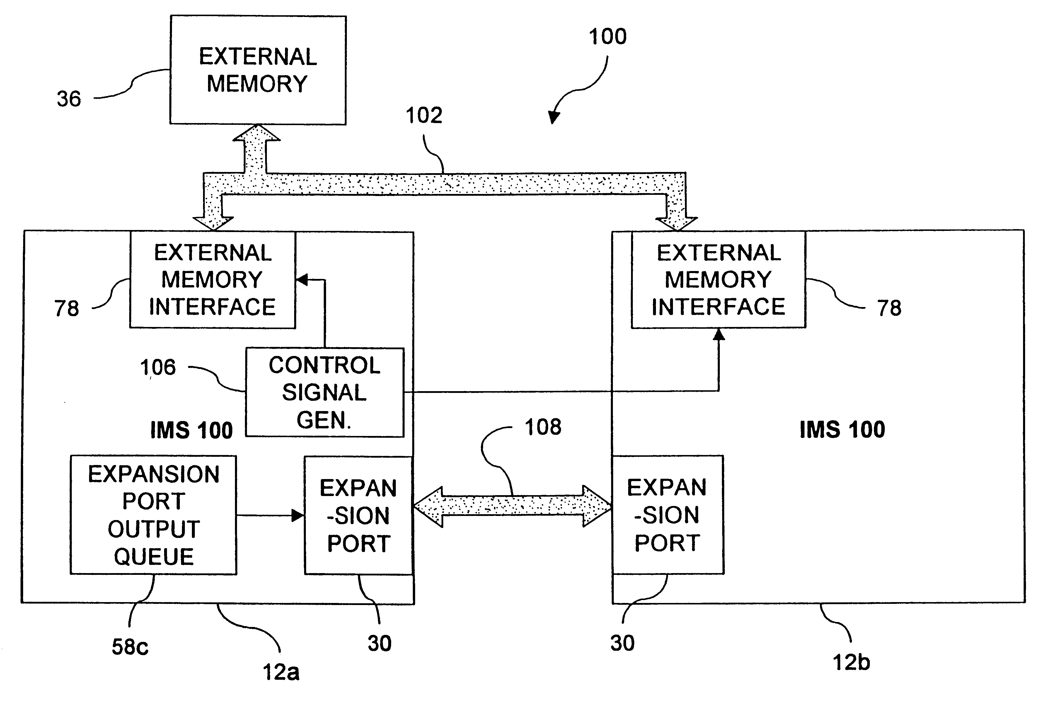
First, an exemplary switched network arrangement will be discussed to provide an understanding of the particular network switches used in the present invention. Following this discussion will be a detailed description of an arrangement and method according to a preferred embodiment of the present invention comprised of a network switch arrangement utilizing a shared external memory.

Switch Architecture Overview

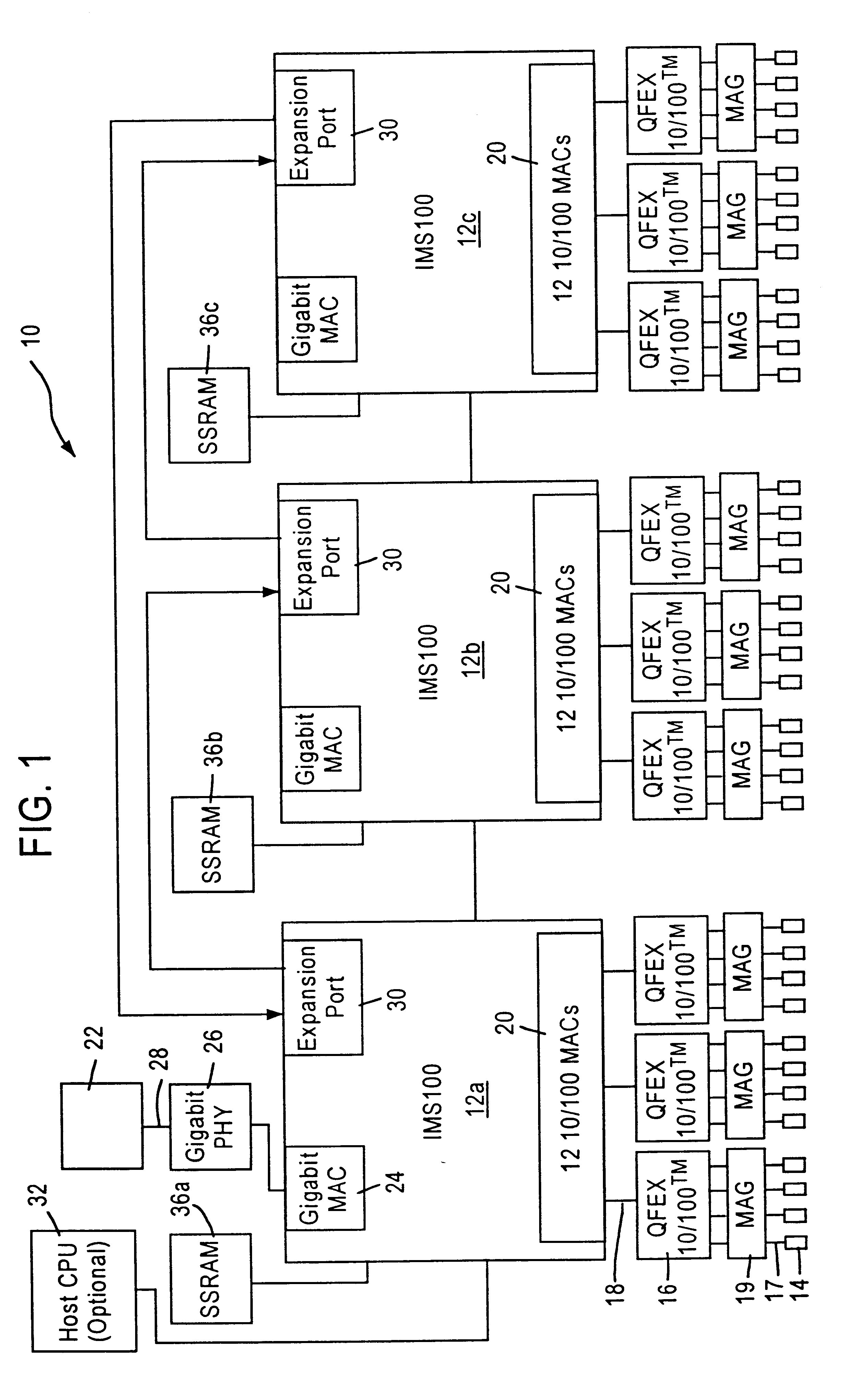
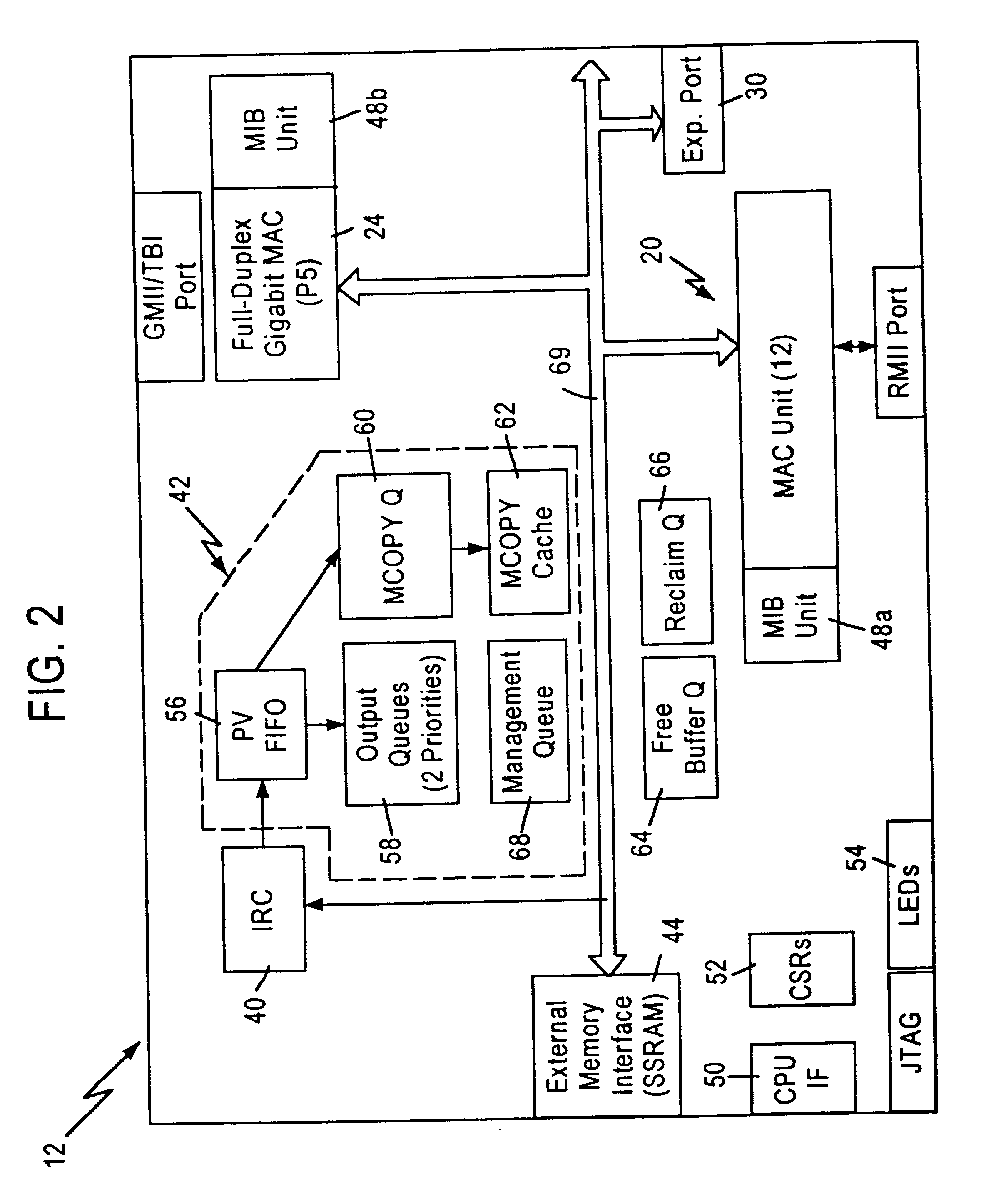
FIG. 1 is a block diagram of an exemplary system in which the present invention may be advantageously employed. The exemplary system 10 is a packet switched network, such as an Ethernet (IEEE 802.3) network. The packet switched network includes integr...


PUM


Abstract

A non-blocking network switch arrangement of plural network switches provides a single, shared external memory for the network switches. Each network switch in the arrangement may write data frames to a respective predetermined portion of the external memory allocated to each switch. When accessing the external memory, each network switch may access any portion of the external memory to transfer data frames to other network stations. Thus, data frames are accessed by each switch in the arrangement directly from the single, shared external memory, thereby eliminating the potential for blocking due to transfer of data frames from the memory of one switch to the memory of another switch.

Description

1. Field of the InventionThe present invention relates to networks and more particularly, to an apparatus and method of storing and controlling network traffic data in a switched network operating according to Ethernet (IEEE 802.3) protocol.2. Background ArtSwitched local area networks use network switches for supplying data frames between network stations or other network nodes, where each network node is connected to a network switch by a media. The switched local area network architecture uses a media access control (MAC) enabling a network interface within each network node and the network switch to access the media. Each network switch stores and forwards data frames received from a transmitter node to a destination node based on header information and the data in the received frames, including a source and destination address. Each network switch uses a respective external memory, such as an SSRAM, to temporarily store data frames as they are passed through the switch. In part...

Claims


Application Information

Patent Timeline
Patent Type & Authority Patents(United States)
IPC IPC(8): H04L12/56H04L12/44
CPCH04L12/44H04L49/90H04L49/9073H04L49/205H04L49/3018H04L49/3027H04L49/351H04L49/352H04L2012/445
Inventor ERIMLI, BAHADIR
Owner GLOBALFOUNDRIES INC
Why Eureka
Try Eureka