Gas analyzer and a method for operating the same

a gas analyzer and gas analyzer technology, applied in the field of gas analyzer and a method for operating the same, can solve the problems of toxic or corrosive or combustible measuring gas, damage already occurring before the service staff, and high cost of specialists employed, so as to improve safety

Inactive Publication Date: 2002-11-26
ABB PATENT GMBH
View PDF22 Cites 6 Cited by
  • Summary
  • Abstract
  • Description
  • Claims
  • Application Information

AI Technical Summary

Benefits of technology

to improve a gas analyzer and a method for operating such in order substantially to improve safety both in handling corrosive and / or combustible and / or toxic gases in a not potentially explosive atmosphere (ex-free atmosphere) and in the operation of such an analyzer in an ex-atmosphere.
With reference to a method for operating such a gas analyzer, it is provided according to the invention that in the case of analysis of a toxic or corrosive or combustible gas a space arranged around the analysis or sensor unit is flowed around or through by a purging gas, an overpressure being set in the purged space by comparison with the analysis gas space. Consequently, for safety reasons, appropriate pressure gradients are set up which reliably prevent leakage gas from escaping into the purging gas path and thus into the environment.
It is advantageously provided, furthermore, that purging is performed via a regulator by virtue of the fact that fractions of toxic or corrosive or combustible gas components in the purging gas can be detected by a sensor and, thereupon, the throughput of purging gas can be increased under regulation.
FIG. 2 shows a gas analyzer having a sensor unit and a processing unit in a housing 20. A non-explosive (for example intrinsically safe) sensor is arranged in a first sensor chamber 30 for the case in which only combustible gas is used. The toxic or corrosive or combustible measuring gas is introduced into this sensor chamber 30 and extracted therefrom. The sensor chamber 30 is surrounded in the way according to the invention by a second chamber 40 which can optionally be purged. This second chamber 40 is a hermetic space between the sensor 30 chamber 30 and the housing 20 containing the electronic system. The escape of corrosive or toxic or combustible gas towards the analyzer is thereby prevented. The purging gas system operates in the same way as already mentioned in the above-named example.

Problems solved by technology

In chemical process engineering, however, it is frequently necessary to solve measurement tasks in which one or more gas components in corrosive and / or toxic and / or combustible gases are to be analyzed.
For this purpose, expensive use is made of specialists who are employed in potentially explosive atmospheres (ex-atmospheres) and also in corrosive and toxic gases together with housing purging (pressurized enclosure) and a pressure tight enclosure, that are to be monitored.
It frequently happens that some damage has already occurred before the service staff can intervene.
If a leak were to occur in this case through the first chamber, toxic or corrosive or combustible measuring gas would flow via this leakage only into the second chamber, which is, in turn, purged permanently by an inert gas.
Firstly, the purging gas must be inert or have at least essentially such properties, and, secondly, it is not permitted to effect any appreciable absorption of that radiation band which is directed sensitively to the measuring gas.

Method used


Image

  • Gas analyzer and a method for operating the same
  • Gas analyzer and a method for operating the same
  • Gas analyzer and a method for operating the same

Examples


Embodiment Construction

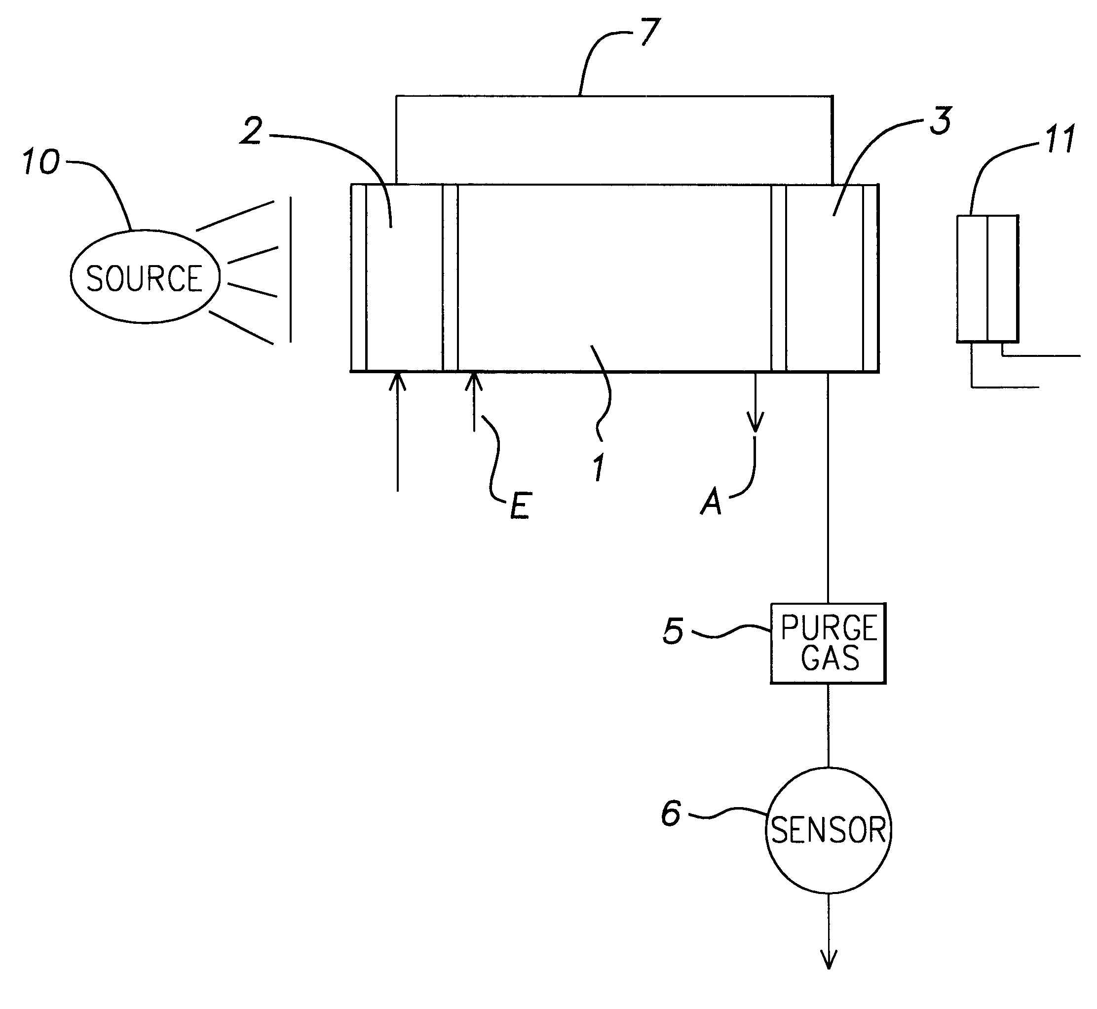
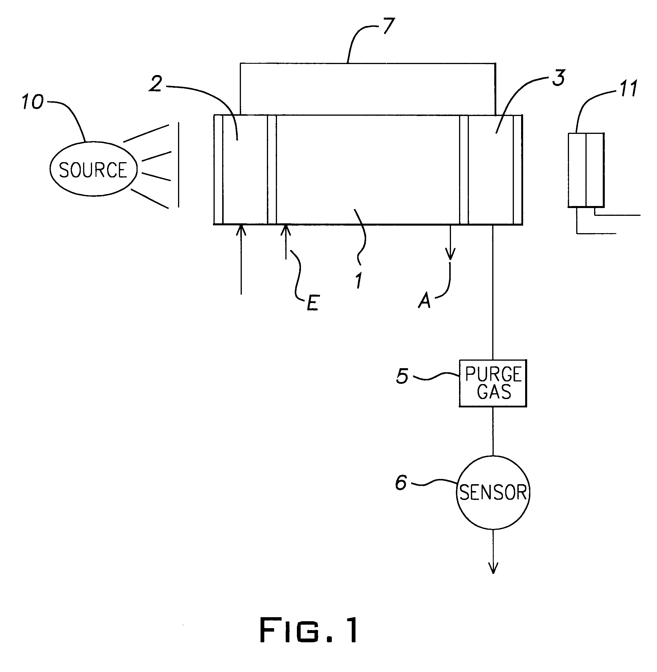
FIG. 1 shows the use of the invention in terms of apparatus in the case of absorption photometry, by way of example. In this case, the system purged by the measuring gas is the measuring cuvette 1 as such. The latter comprises a tubular element having a measuring gas input E and a measuring gas output A. The entry window for the radiation from a radiation source 10 is in the region of the inlet E, and the outlet window for the radiation passing the cuvette is in the region of the measuring gas exit A, said radiation then being led to the detector 11.

Overall, the cuvette 1 is surrounded respectively by a second chamber 2, 3, at least in the region of the entry and outlet windows. Since otherwise the cuvette comprises a closed metallic tube, leakages can occur only at the built-in windows. Consequently, a purging chamber can be provided only upstream of the entry window, and a purging chamber can be provided upstream of the exit window. In this case the two component chambers 2, 3 are...


PUM

PropertyMeasurementUnit
optical gas analysisaaaaaaaaaa
pressureaaaaaaaaaa
partial pressure fractionaaaaaaaaaa

Abstract

A gas analyzer having an analysis or sensor unit and having an electronic processing unit, and a method for operating such a gas analyzer. In order to achieve substantially improved safety both in handling corrosive and / or combustible and / or toxic gases in a not potentially explosive atmosphere (ex-free atmosphere), and in the operation of such an analyzer in an exatmosphere, the analysis or sensor unit as such is of non-explosive configuration and is arranged in a gas tight chamber through which a toxic and / or corrosive and / or combustible gas flows and around which a second chamber is arranged.

Description

This invention relates to a gas analyzer having an analysis or sensor unit and having an electronic processing unit, and to a method for operating such a gas analyzer.DESCRIPTION OF THE PRIOR ARTMany versions, and also many operating methods, are known for gas analyzers having a sensing unit and an electronic processing unit. In this case, use is made of gas sensors which, depending on configuration, are sensitively set to one or other gases depending on which one is desired for selective measurement. Electronic sensor systems, gel sensors, thermal conduction sensors and other similar sensors are known for this purpose. Solid electrolyte sensors are also known, in particular for oxygen analysis.Also known, however, over and above this are optical gas analysis methods in the case of which a cuvette flowed through by measuring gas is transradiated starting from a light source of specific radiation bands. Arranged on the side of the cuvette opposite the light source is a detector which...

Claims


Application Information

Patent Timeline
Patent Type & Authority Patents(United States)
IPC IPC(8): F23J15/00G01N21/01G01N9/00G02B6/00G01N21/09
CPCG01N21/09
Inventor FABINSKI, WALTERSCHASTOK, PETERTHIES, WERNER
Owner ABB PATENT GMBH
Why Eureka
Try Eureka