Method relating to a polishing system having a multi-phase polishing layer

a technology of polishing system and polishing layer, which is applied in the direction of lapping machines, other chemical processes, instruments, etc., can solve the problems of reducing affecting the polishing efficiency and performance, and requiring extensive cleaning of substrates and polishing equipmen

Inactive Publication Date: 2002-12-03
ROHM & HAAS ELECTRONICS MATERIALS CMP HLDG INC
View PDF15 Cites 62 Cited by
  • Summary
  • Abstract
  • Description
  • Claims
  • Application Information

AI Technical Summary

Benefits of technology

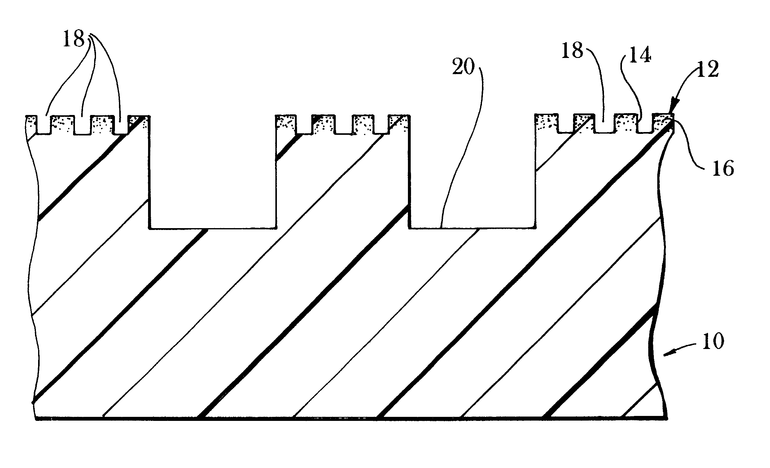
To provide consistency of polishing performance, any polishing pad flow channel(s) should have a configuration whereby as the pad wears to one half the average depth of the largest flow channel, the amount of surface area capable of contacting the substrate changes by less than 30%, more preferably less than 10% and most preferably less than 5%.

Problems solved by technology

With conventional polishing systems, such particle dispersion uniformity (at the polishing interface) is very difficult to achieve, particularly during initial polishing ("start-up").
Non-uniformity of particles at the polishing interface generally lowers polishing efficiency and performance.
However with such conventional polishing systems, the substrate and polishing equipment generally require extensive cleaning after the polish.
This cleaning step slows down production, is prone to operator error and can create environmental concerns.
High modulus phase materials, particularly sub-micron ceramic particles tend to agglomerate into much larger sized particles, and this can be a problem, when creating the an high modulus phase of the present invention.
Such particle agglomeration can lead to scratching and can adversely affect polishing performance.
When filler loadings are high, the particles are generally not fully surrounded by the polymer, creating a relatively brittle material.
High glass transition temperature polymers tend to produce brittle matrices rendering the material relatively friable.
For instance, high loading increases friability.
In such an embodiment, the polymerization reaction should induce adhesion between the substrate and matrix material, and the substrate should be prone to surface wetting by the precursor matrix material.
High loadings of the high modulus phase will generally decrease pad life, since high loadings of the high modulus phase material will tend to release rigid domains and as these domains are released, the pad wears away.
Such a decrease in pad conditioning is advantageous, because conditioning slows production, is labor intensive and presents an opportunity for operator error.

Method used


Image

  • Method relating to a polishing system having a multi-phase polishing layer
  • Method relating to a polishing system having a multi-phase polishing layer

Examples


example 1

This example describes one embodiment of particle cluster fabrication according to the present invention. A formulation was prepared having 5 weight percent A-100* and 95 weight percent CeO.sub.2 **. A 1935 g CeO.sub.2 aqueous dispersion (the concentration of CeO.sub.2 in the dispersion was 21.5% ) was prepared and poured into a mixer. Using high shear mixing, 63 g of an aqueous dispersion of A-100 (concentration of 55%) was slowly added to the CeO.sub.2 dispersion. Mixing continued for 30 min. The resulting mixture was poured into an aluminum pan and heated for fourteen hours at 60.degree. C. until dried. The dried mixture was ground by mortar and pestle to a fine powder. Each grain of powder represented a particle cluster.

*A-100--a water based colloidal dispersion of urethane and polyacrylate copolymer manufactured by Witco, Inc.

**CeO.sub.2 --water dispersion with a primary particle size of 200 nm , manufactured by Mitsui Chemical Company.

example 2

This example describes a dispersion of particle clusters in an inter-cluster polymer.

Table 2. Weight Percent of Cluster / Interpolymeric Binder Formulation

Three-hundred grams of a W-242 aqueous dispersion, 157.5 g of particle clusters produced as in Example 1, 6.0 g of XW, 9.0 g of surfactant and 100 g deionized water were mixed in a laboratory jar-mill (with zirconia as a ball-mill medium) for fourteen hours. A spray-gun was used to spray the mixture on the surface of a grooved IC-1400 pad (polishing pad manufactured by Rodel, Inc., Newark, Del.). After spraying, the pad was heated in an oven at 60.degree. C. for fourteen hours.

.sup..times. W-242 urethane aqueous dispersion manufactured by Witco, Inc.

.sup..times..times. XW epoxy aqueous dispersion manufactured by Witco, Inc.

.sup..times..times..times. Velvetex BK-35 surfactant manufactured by Henkel Corporation

example 3

This example describes one embodiment for a method of polishing. Thermal oxide wafers were polished using a polishing pad prepared in Example 2. The pad was mounted on a Strasbaugh 6CA polishing machine platen. The pad was rinsed with de-ionized water and conditioned with 200 grit diamond grid for 3 min. A particle-free polishing slurry (NH.sub.4 OH (1.7%) in water) was introduced on the surface of the pad at a rate of 100 ml / min. A platen speed of 60 rpm and a quill speed of 50 rpm were used. The pressure between the pad and the wafer was 8 psi. The wafer was polishing for 2 min. then rinsed with deionized water for 30 seconds. Seventy-five thermal oxide wafers were polished with one pad. There was no reconditioning between wafers. An average removal rate of 3000-3500 .ANG. / min was achieved.

Pad Plus Slurry

The polishing systems of the present invention comprise the (above described) polishing pad design in combination with a polishing slurry. Any particle containing polishing fluid ...


PUM

PropertyMeasurementUnit
diameteraaaaaaaaaa
radiusaaaaaaaaaa
particle sizeaaaaaaaaaa

Abstract

A method of making a polishing pad composition comprising a high modulus phase component and a low modulus phase component, and a method of polishing a semiconductor substrate by creating nanoasperities at a polishing interface between the polishing layer and the wafer during polishing by providing the high modulus phase component at the polishing interface, either as protrusions from the polishing layer, or by being released from the polishing layer into the polishing interface.

Description

The present invention relates generally to high performance polishing systems for use in modifying a substrate by Hertzian indentation, fluid-based wear and / or any similar-type non-microgrinding mechanism; the polishing systems of the present invention are particularly well suited for use in the manufacture of semiconductor devices or the like. More particularly, the compositions and methods useful in the method of the present invention are directed to polishing systems comprising an aqueous based polishing fluid and a polishing pad; the polishing pads of the present invention comprise a polishing layer having two separate phases: a high modulus phase and a low modulus phase.Definition of Terms1. Polishing. "Polishing" is intended to mean chemical-mechanical polishing (as opposed to micro-grinding) and is intended to include planarization and any corresponding variations thereof. The polishing substrates contemplated by the present invention include semiconductor device substrates, ...

Claims


Application Information

Patent Timeline
Patent Type & Authority Patents(United States)
IPC IPC(8): B24D3/34B24D3/20B24D3/28B24B41/00B24B37/04B24B41/047B24D13/10B24D13/00B24D13/14H01L21/02H01L21/306G11B23/00B24B37/26
CPCB24B37/26B24B41/047B24D3/28B24D3/34B24D13/10H01L21/30625G11B23/0021
Inventor JAMES, DAVID B.BUDINGER, WILLIAM D.ROBERTS, JOHN V. H.OLIVER, MICHAEL R.CHECHIK, NINA G.LEVERING, JR., RICHARD M.COOK, LEE MELBOURNE
Owner ROHM & HAAS ELECTRONICS MATERIALS CMP HLDG INC
Why Eureka
Try Eureka