Reconfigurable antenna device for a telecommunication station

a technology of telecommunication station and antenna device, which is applied in the direction of diversity/multi-antenna system, polarisation/directional diversity, individually energised antenna array, etc., can solve the problems of affecting the spatial selectivity of the system, affecting the system selection, and affecting the spatial selection of the system

Inactive Publication Date: 2002-12-17
MITSUBISHI ELECTRIC CORP
View PDF6 Cites 36 Cited by
  • Summary
  • Abstract
  • Description
  • Claims
  • Application Information

AI Technical Summary

Problems solved by technology

Thus signals which have propagated on several paths as far as a first antenna (the first diversity branch) giving rise to destructive interference can on the other hand give rise to constructive interference at another antenna (the second diversity branch).
The antenna arrays as mentioned above do not deal well with spatial diversity f...

Method used


Image

  • Reconfigurable antenna device for a telecommunication station
  • Reconfigurable antenna device for a telecommunication station
  • Reconfigurable antenna device for a telecommunication station

Examples


Embodiment Construction

is a simple case where the elementary antennae are grouped by packets with the same size q. The equivalent array pitch is then q*d, where d is the pitch of the basic array. The output signals of the elementary antennae all undergo the same weighting in the grouping units before being summed therein. Below the X-axis line there have been indicated the active grouping units in the form C.sub.z.sup.j where j is the index of the active unit 620.sub.j and z is a subset of (-k,-k+1, . . . ,0, . . ,k-1,k) of the connections adopted for the weighting, the others being multiplied by a zero coefficient or inhibited. Example B shows the design of an equivalent array with a pitch of the form (2p+1)d / 2 where p is an integer. The array is simulated by alternating the packets of p and p+1 elementary antennae. The difference in weighting level between the packets of p and p+1 elements is due to the standardisation according to the number of elementary antennae per packet. Finally, example C illustr...


PUM


Abstract

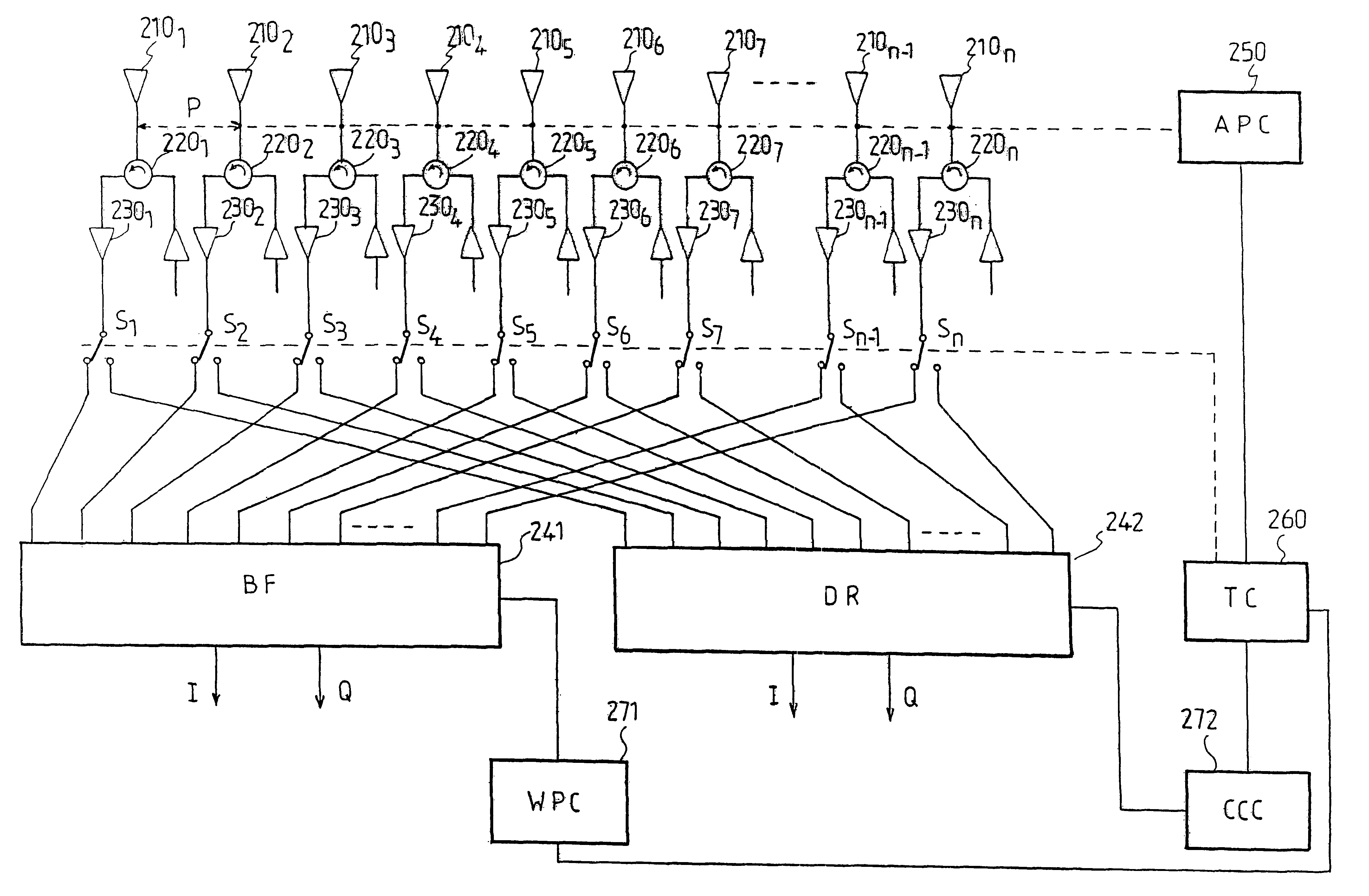
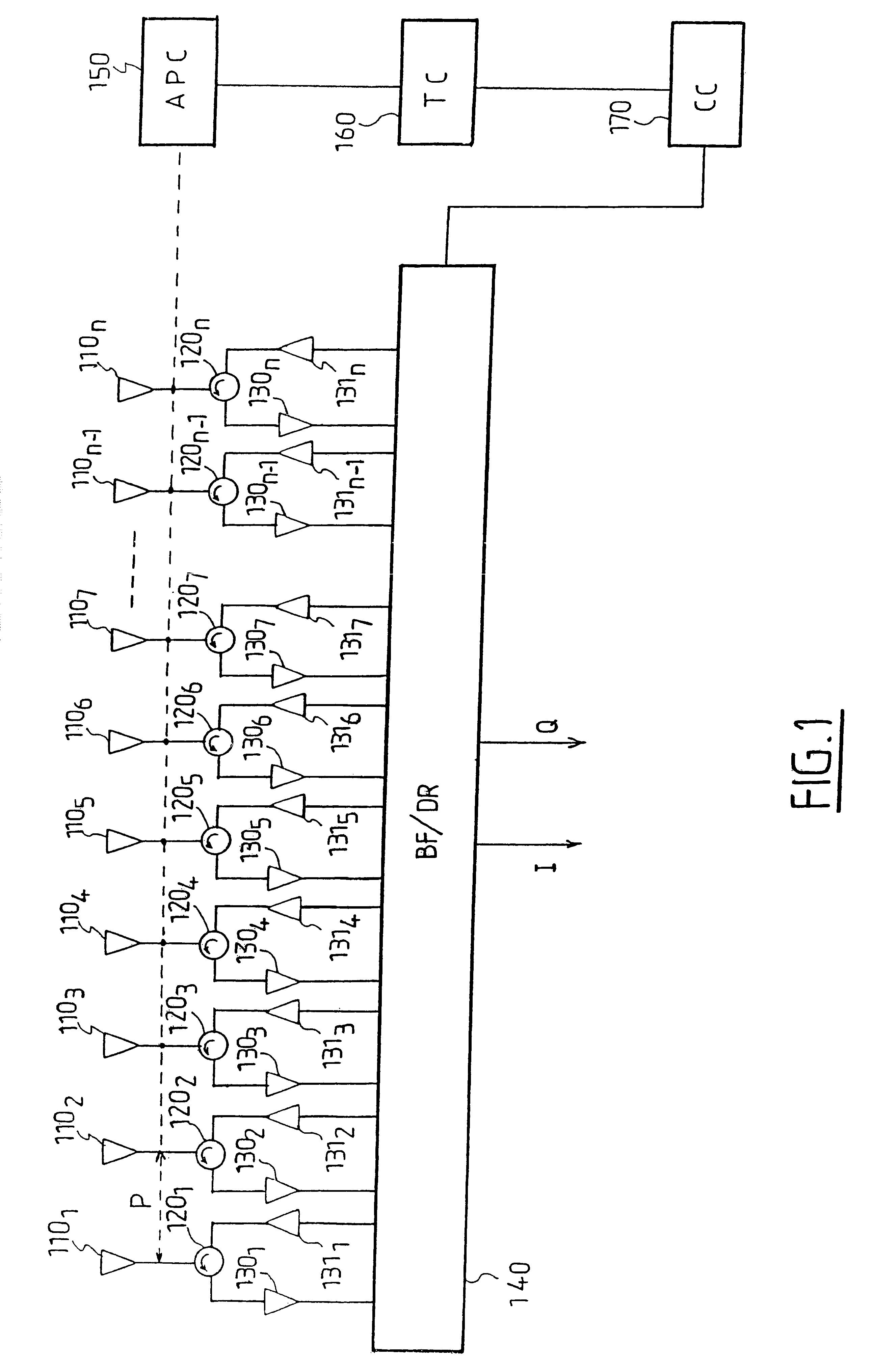
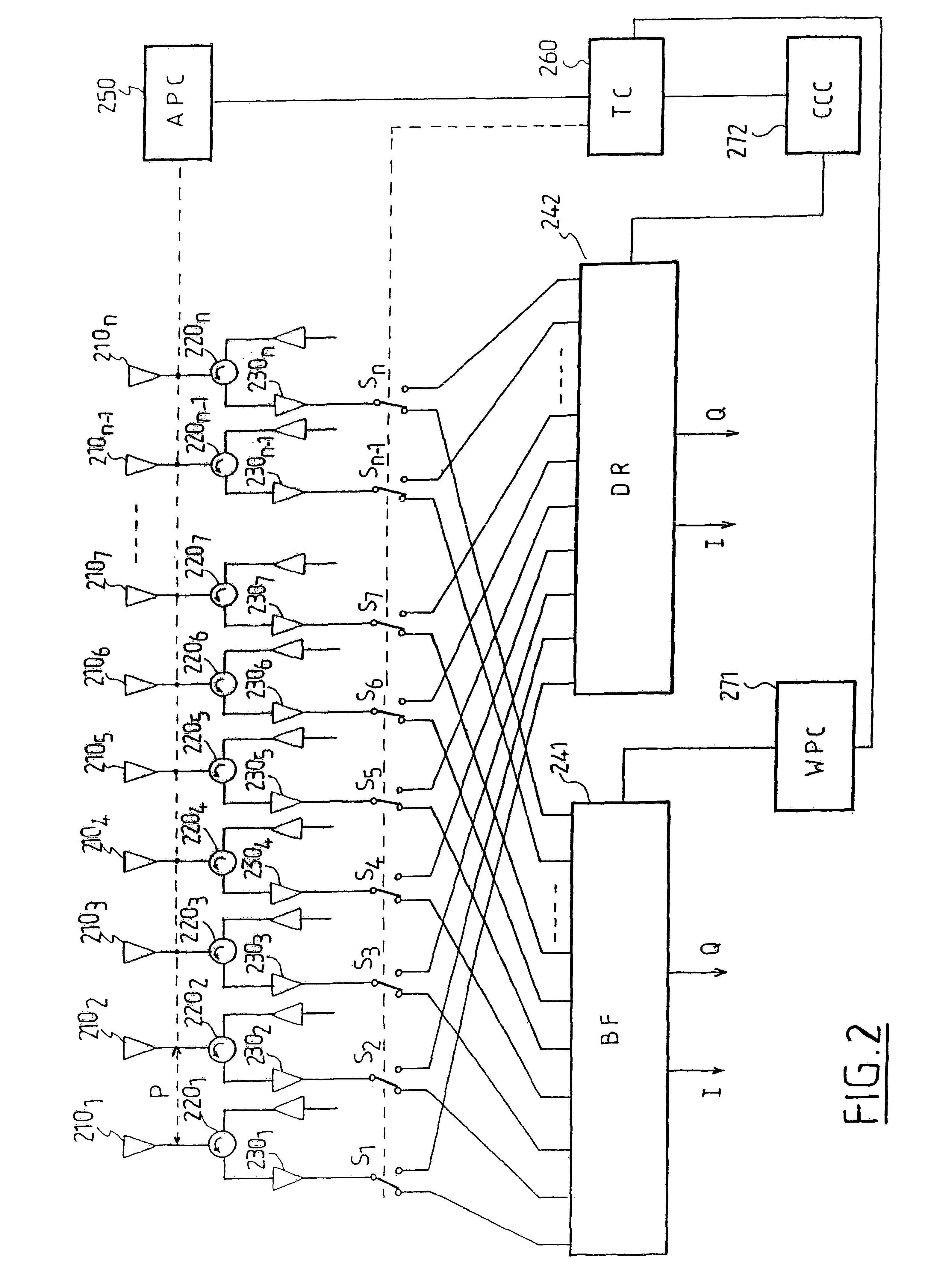
The invention in general terms relates to an antenna device for a telecommunication station, able to transmit or receive a signal and comprising a plurality of radiating elements disposed in a periodic arrangement having at least one spatial periodicity. The device has antenna configuration means adapted to cause the value of the said spatial periodicity to vary according to the transmission conditions. The antenna device can in particular be configured so as to operate according to a beam shaping mode or according to a spatial diversity mode.

Description

1. Field of the InventionThe present invention concerns in general terms an antenna device, notably for a telecommunication station, and more particularly an antenna device comprising a periodic arrangement of radiating elements.2. Description of Related ArtRecent developments in antenna systems for mobile telephony have revealed an increasing interest in so-called "intelligent" antennae. Such an antenna consists of a array of elementary antennae with a pitch less than or equal to the half-wavelength of the transmission frequency, which can be used both for transmission and for reception. Depending on circumstances, the input or output signals of the elementary antennae are offset in phase and weighted so as to obtain the required radiation diagram. Thus, for example, an intelligent antenna equipping a base station can form a beam pointing in the direction of a mobile terminal and / or eliminate interference coming from a given direction.There are also known mobile telephony systems r...

Claims


Application Information

Patent Timeline
IPC IPC(8): H01Q3/22H01Q1/24H01Q3/04H01Q3/02H01Q21/22H01Q21/08H01Q3/24H01Q3/26H04B7/06H04B7/10
CPCH01Q1/246H01Q3/04H01Q3/22H01Q21/08H01Q21/22
Inventor MOTTIER, DAVID
Owner MITSUBISHI ELECTRIC CORP
Why Eureka
Try Eureka