Apparatus and method for measuring the pressure distribution generated by a three-dimensional object

a three-dimensional object and apparatus technology, applied in the field of apparatus and method for measuring the pressure distribution generated by a three-dimensional object, can solve the problems of reducing the electrical resistance of the sensor, prone to inaccurate readings of the pneumatic and hydraulic sensor, and disadvantageous sensors

Inactive Publication Date: 2003-01-14
RSSCAN
View PDF8 Cites 99 Cited by
  • Summary
  • Abstract
  • Description
  • Claims
  • Application Information

AI Technical Summary

Problems solved by technology

Pneumatic and hydraulic sensors are prone to produce inaccurate readings because changes in internal pressure are not necessarily proportional to change in forces.
However, these sensors are disadvantageous due their bulkiness and weight.
The sensors which measure mechanical deformation of structural elements supporting the wearer's foot by use of electrical wire or ribbon type strain gauges accurately measure weight, but they are also disadvantageous because of their bulk and weight.
In direct electronic force sensor devices, the applied pressure compresses a partially conductive material (carbon granules) and thereby reduces its electrical resistance.
Such thin film electronic force sensors have the advantages of simplicity, compactness, and light weight, but the disadvantage that they only provide relative indications of pressure applied.
These sensor arrays are very thin and very light weight, but they cannot conform to a compound curved surface without wrinkling.
Such wrinkled or folded thin film sensor arrays may produce erroneous results.
Folding or wrinkling also subjects the sensor array to severe fatigue stress, which can lead to early and sudden failure.
The problem of electrically connecting this number of individual sensors to data acquisition circuitry is a significant one.
However, the major disadvantage of resistive pressure sensors is that they are not absolutely calibrated but rather provide relative pressure values.
Calibrating or re-calibrating the multitude of pressure sensors in a pressure pad is not only time consuming but also difficult to carry out exactly.
As the pressure pad is not absolutely rigid, it is difficult to apply a uniform pressure to individual or groups of sensors.

Method used


Image

  • Apparatus and method for measuring the pressure distribution generated by a three-dimensional object
  • Apparatus and method for measuring the pressure distribution generated by a three-dimensional object
  • Apparatus and method for measuring the pressure distribution generated by a three-dimensional object

Examples


Embodiment Construction

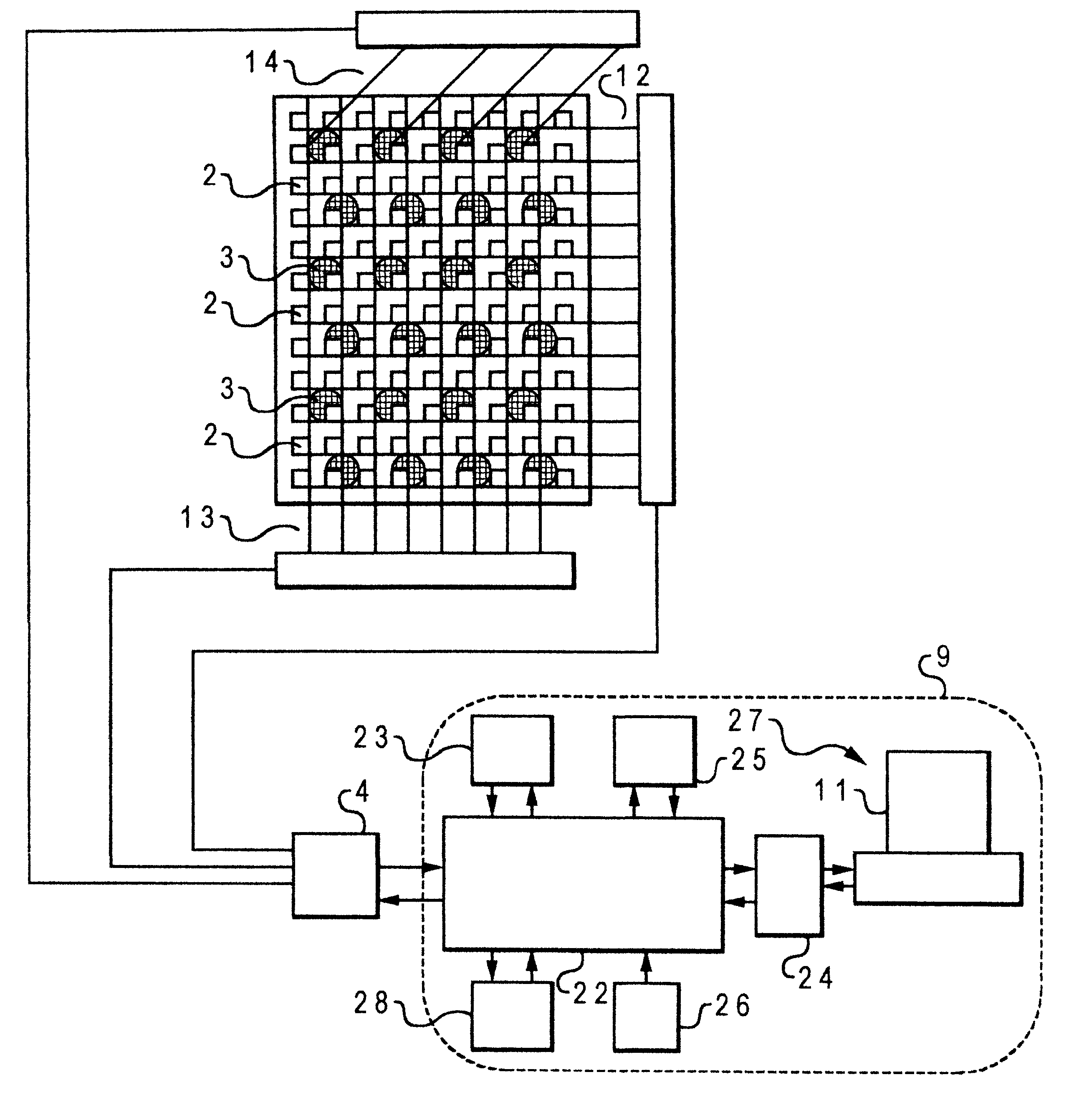
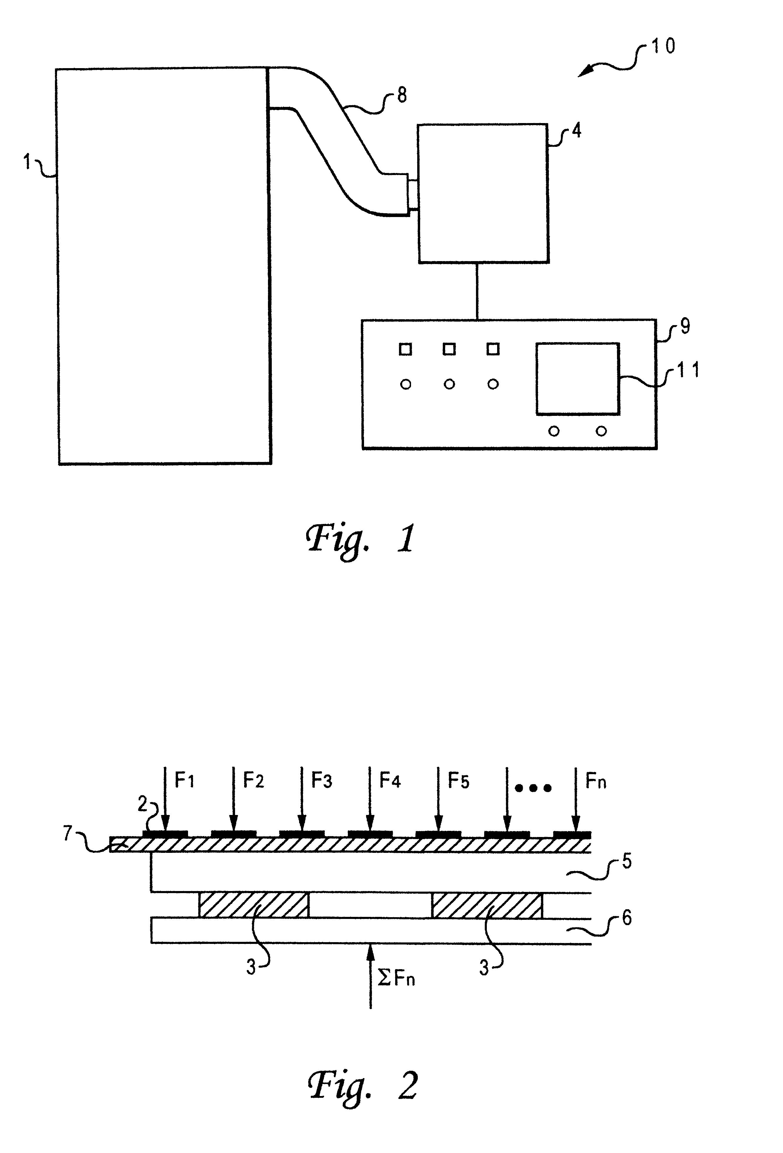
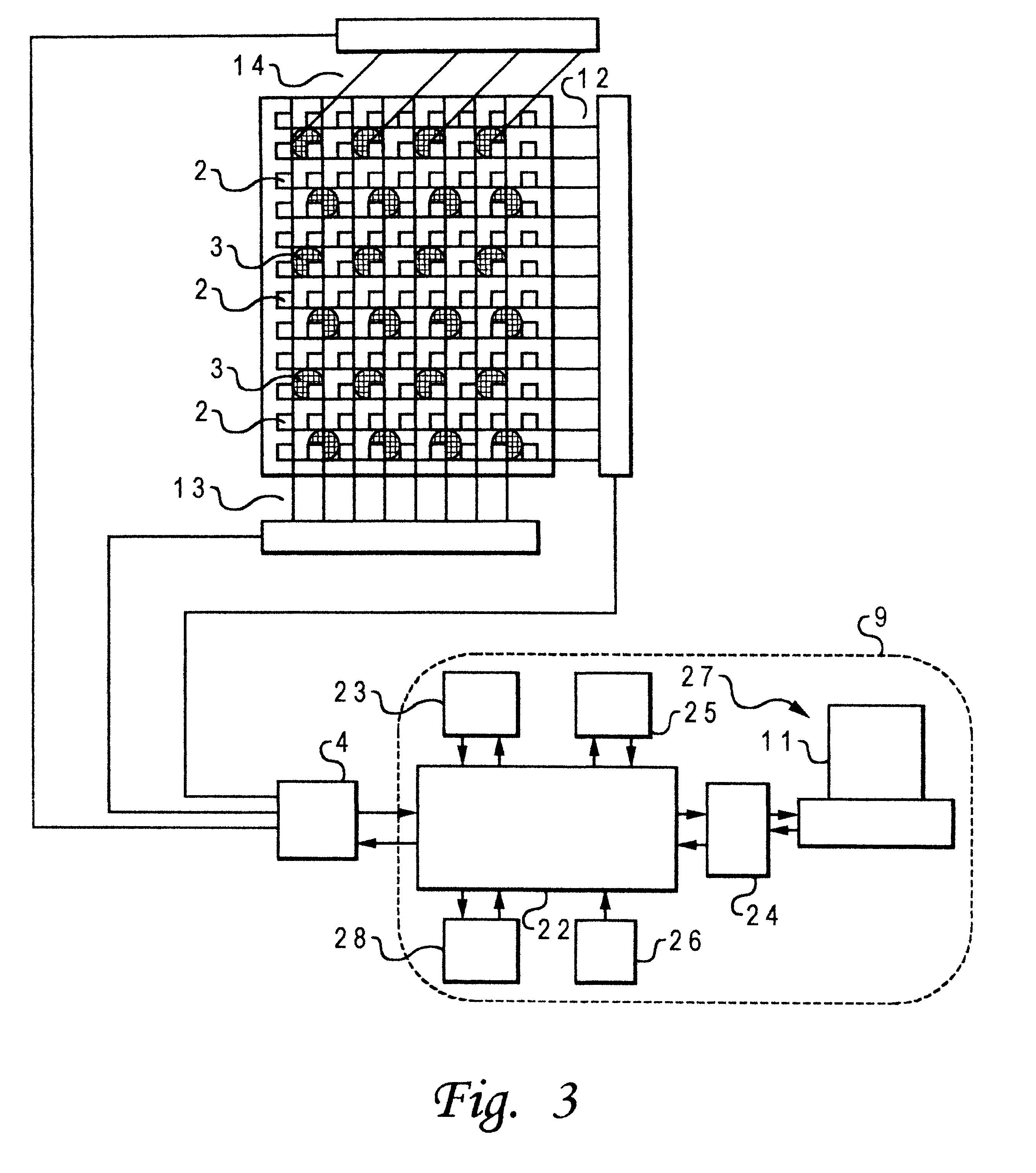
The present invention will be described in the following mainly with respect to a device for measuring the pressure and / or force on the feet of human beings or animals during walking, running, jumping or standing. The invention is not limited thereto but may be used for the measurement of the pressure distribution generated by any three-dimensional object. Further, the present invention will be described mainly with respect to the use of an array of resistive force sensors, but the present invention is not limited thereto. Alternative force sensing devices may be used, for instance capacitive or inductive force sensing devices. Further, the present invention will be described mainly with respect to the use of piezo-electric sensors as the second sensing device for measuring the total force on the intermediate plate. The present invention is not limited thereto but includes other force or pressure sensing devices, in particular strain gauge and piezo-resistive force sensing devices w...


PUM

PropertyMeasurementUnit
weightaaaaaaaaaa
pressure distributionaaaaaaaaaa
total forceaaaaaaaaaa

Abstract

A self-calibrating apparatus and a self-calibrating method for measuring the pressure distribution generated by a three-dimensional object, is described which includes a plurality of first non-linear force sensors arranged in an array; and a second force sensing device (3) having a linear or linearisable output for measuring the total force applied to the first force sensors. The first sensors are dynamically calibrated based on the results of the comparison. The three-dimensional object may be a human foot and the apparatus and method amy be sued for fitting shoes or for determining irregularities or ailments of the human foot or leg.

Description

The present invention relates to an apparatus and a method of measuring the pressure distribution generated by a three-dimensional object, in particular the feet of humans or animals. The present invention is particularly useful in the diagnosis of leg and foot abnormalities and in the selection and design of foot wear.TECHNICAL BACKGROUNDSeveral devices have been designed to measure forces applied by the foot. These include devices for measuring applied forces that are attached to the foot during walking or running, for measuring peak pressure, for measuring the total force applied by the foot, and for measuring forces applied by certain areas of the foot for various purposes. Other devices employ a stationary foot sensor pad and are suited for use in a laboratory or hospital.Conventional foot force measurement devices function to convert mechanical force into a suitable electrical signal. The types of sensors used include pneumatic or hydraulic fluid activated switches, strain gau...

Claims


Application Information

Patent Timeline
Patent Type & Authority Patents(United States)
IPC IPC(8): A61B5/103G01L1/20
CPCG01L1/205A61B5/1036
Inventor WILSSENS, JEAN-PIERRE
Owner RSSCAN
Why Eureka
Try Eureka