Recording sheet feeding device

a technology of feeding device and recording sheet, which is applied in the direction of thin material processing, article separation, article delivery, etc., can solve the problems of density unevenness in the recording sheet, deviation in the exposed position, and possibility of density unevenness in the print imag

Inactive Publication Date: 2003-01-14
FUJIFILM CORP +1
View PDF13 Cites 16 Cited by
  • Summary
  • Abstract
  • Description
  • Claims
  • Application Information

AI Technical Summary

Benefits of technology

The capstan rollers and the pinch rollers are covered with elastic members, such as silicon rubbers. Between the first and second capstan rollers is disposed a guide member which has a guiding surface for supporting the recording sheet. The guiding surface is located to be 0.01 mm to 0.08 mm lower than the top level of the first and second capstan rollers. When the recording sheet is nipped by the feeding roller pair, the elastic member of the capstan roller is deformed such that the top level of the capstan roller becomes the same level as the guiding surface. Moreover, the guide member has plural guiding projections extended in a feeing direction of the recording sheet. The guiding projections are tapered off and fit into the orbital grooves of the capstan rollers. This ensures smooth conveyance of the recording sheet.
According to the present invention, the orbital grooves of the pinch rollers, shallower than those of the capstan rollers, are able to relax the strain of the recording sheet in the widthwise direction, and to suppress the curls of the recording sheet. Since the recording sheet is not deviated from the proper position, recording light beams from a recording device are applied to proper positions on the recording sheet, so exposure unevenness in the recording sheet can be prevented.

Problems solved by technology

When passing the first feeding roller pair, however, the trailing end of the recording sheet is bent upward or downward, which causes deviation in exposed position.
In that case, density unevenness in the recording sheet could be occurred.
Moreover, before passing the second feeding roller pair, the leading end of the recording sheet is curled, so there is a possibility to occur density unevenness in a print image, as mentioned above.
When positioned between the roller bodies, the both lateral ends of the recording sheet is curled, which causes exposure unevenness, as set above.

Method used


Image

  • Recording sheet feeding device
  • Recording sheet feeding device
  • Recording sheet feeding device

Examples


Embodiment Construction

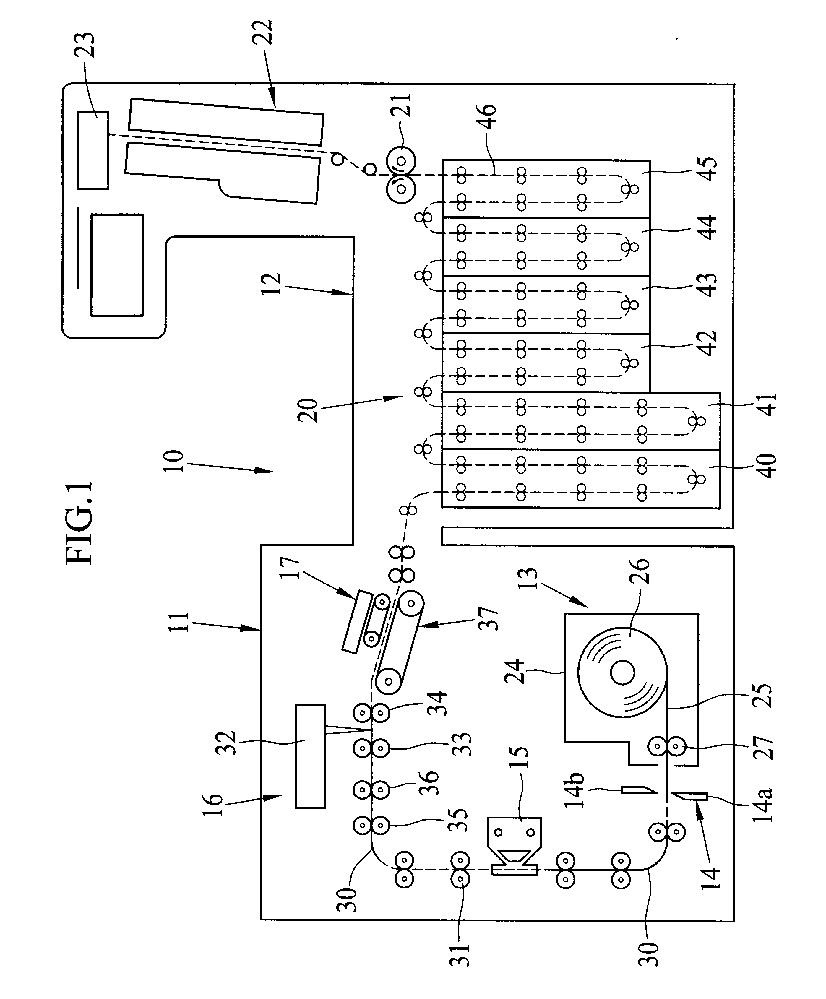
In FIG. 1, a printer processor 10 is comprised of a printer section 11 and a processor section 12, which are connected to each other. The printer section 11 includes a paper loader 13, a paper cutter 14, a rear side printer 15, an exposure unit 16 and a sheet sorter 17. The processor section 12 includes a development / fixation device 20, a squeeze roller pair 21, a drier 22 and a sheet collection unit 23.

A paper magazine 24 is loaded in the paper loader 13, and includes a photosensitive recording paper 25, which is wound into a paper roll 26. For instance, the photosensitive paper is formed by coating a mixture of a white pigment and a resin including a polyester, on an emulsion-coated surface (recording surface) of a base sheet. The paper magazine 24 is provided with a feeding roller pair 27, which is driven by a feeding motor (not shown). When the feeding roller set 27 rotates, the photosensitive recording paper 25 is drawn from the paper roll 26, and fed to the rear side printer 1...


PUM


Abstract

First and second feeding roller pairs are disposed at positions upstream and downstream of a recording position to record an image onto a recording sheet. Each of the first and second feeding roller pairs includes a capstan roller and a pinch roller, which are located below and above a passage of the recording sheet. The capstan roller and the pinch roller has plural orbital grooves arranged along an axial direction, to relax the strain of the recording sheet with respect to the widthwise direction of the recording sheet. The depth of the orbital grooves of the pinch rollers are set to 0.3 mm, which is shallower than that of the orbital grooves of the capstan rollers. The shallow orbital grooves of the pinch rollers are capable of suppress the curl of the recording sheet effectively.

Description

1. Field of the InventionThe present invention relates to a device for feeding a recording sheet at a certain speed with high precision, preventing exposure unevenness caused by curl of the recording sheet.2. Background ArtsIn a printer processor, for instance, linear recording light beams are applied to a recording area of a photosensitive recording sheet in a main scan direction while the recording sheet is fed in a sub-scan direction perpendicular to the main scan direction, to record an image. Along a passage of the recording sheet are provided a plurality of feeding roller pairs, each of which transfers the recording sheet to the next one. In the vicinity of a record position to which the recording light beams are applied, the recording sheet is nipped by a first feeding roller pair, fed toward the record position, and transferred to a second feeding roller pair. These feeding roller pairs are controlled to be equal in the feeding speed.Each of the first and second feeding roll...

Claims


Application Information

Patent Timeline
Patent Type & Authority Patents(United States)
IPC IPC(8): B65H5/06
CPCB65H5/062B65H2403/514B65H2404/13161B65H2404/1441B65H2553/41B65H2513/10B65H2220/02
Inventor KATO, KENICHIKIMURA, YOUICHI
Owner FUJIFILM CORP
Why Eureka
Try Eureka