
Electromagnetic noise measurement apparatus, electromagnetic noise measurement method and recording medium

a technology of electromagnetic noise and measurement apparatus, applied in the direction of noise figure or signal-to-noise ratio measurement, instruments, transmission monitoring, etc., can solve the problems of no consideration of electromagnetic noise signal generation timing, non-popular quasi-peak measurement method, and social concern for electromagnetic interferen

Inactive Publication Date: 2003-01-21
FUJIFILM BUSINESS INNOVATION CORP
View PDF5 Cites 30 Cited by
  • Summary
  • Abstract
  • Description
  • Claims
  • Application Information

AI Technical Summary

Problems solved by technology

Recently, as electric equipment and electronic equipment spreads, electromagnetic interference becomes an object of social concern.
For these reasons, the quasi-peak measurement method is not popular.
In addition, no consideration has been given to electromagnetic noise signal generation timing which differs according to measurement target apparatuses and to temporarily observed noise.
While a factor with respect to a certain input is precise, a factor with respect to variable inputs tends to be imprecise, with the result that measurement values cannot be often compared with the standard value.
If the respective harmonic components of the specific repetition signal overlap those of a different repetition signal with the same frequency or if the harmonic components of the specific repetition signal are adjacent to those of the different repetition signal, the automatic QP measurement of a measurement target harmonic may sometimes cause an error.
Further, if a measurement system receives a signal having an equivalent intensity for the level of electromagnetic noise radiated from a measurement target apparatus, the measurement system does not always exhibit linearity performance and errors may possibly occur to a measurement result.
Meanwhile, in the QP measurement, a sharp peak waveform which does not continue for a predetermined duration specified by a standard cannot be measured.
As a result, if measurement conditions of the peak field intensity measuring section and the quasi-peak measuring section differ for some reason, there is a possibility that a value measured by the quasi-peak measuring section while automatically measuring the QP value is not correct, which situation will cause erroneous measurement.
However, there are cases where, if these sections are connected in series and regarded as a single processing section, linear input and output characteristics cannot be obtained.

Method used


Image

  • Electromagnetic noise measurement apparatus, electromagnetic noise measurement method and recording medium
  • Electromagnetic noise measurement apparatus, electromagnetic noise measurement method and recording medium
  • Electromagnetic noise measurement apparatus, electromagnetic noise measurement method and recording medium

Examples


first embodiment

The first embodiment according to the present invention will be described.

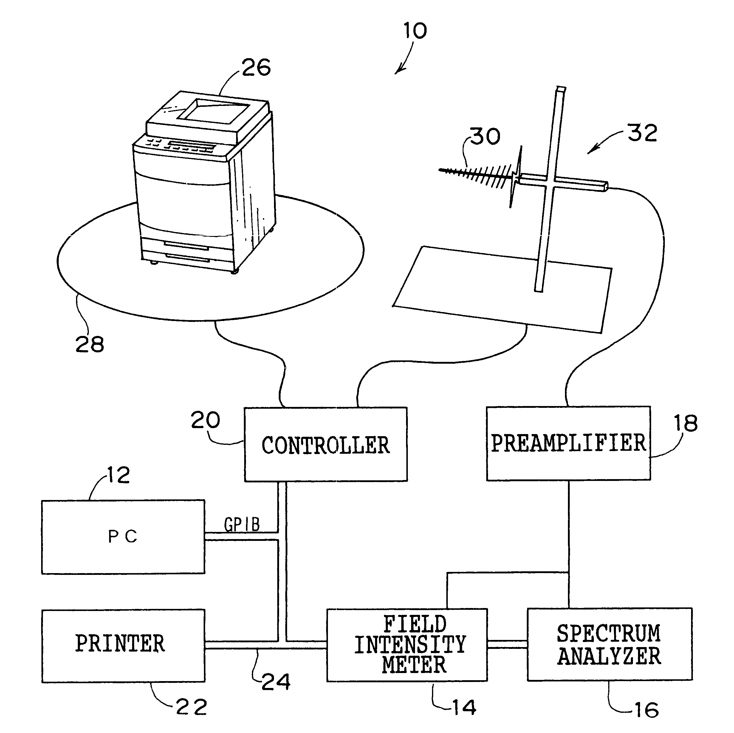
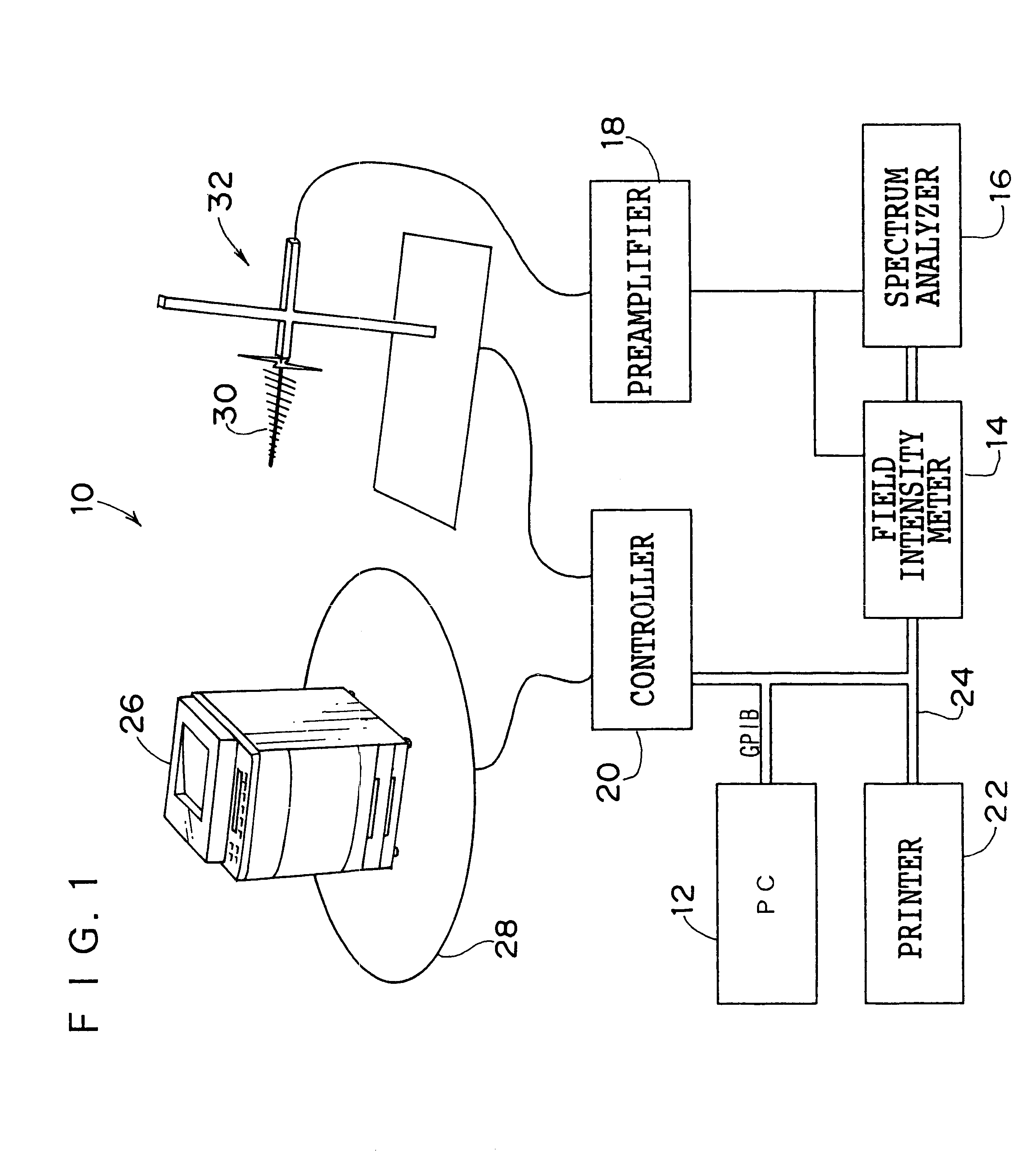
FIG. 1 shows an electromagnetic noise measurement apparatus 10. As shown in FIG. 1, the electromagnetic noise measurement apparatus 10 comprises a personal computer (PC) 12, a field intensity meter 14, a spectrum analyzer 16, a preamplifier 18, a controller 20, a printer 22 and the like. The PC 12, the field intensity meter 14, the spectrum analyzer 16, the controller 20 and the printer 22 are connected to one another by CPIB cables 24.

The controller 20 is connected to an antenna elevator 32 for elevating an antenna 30 for measuring electromagnetic noise radiated from a turn table 28 turning an electromagnetic noise measurement target such as a copying machine 26, and from the copying machine 26. The controller 20 controls the turn table 28 and the antenna elevator 32 according to a command of the PC 12.

Next, description will be given to the measurement (EMI measurement) of electromagnetic noise radiated from ...

second embodiment

The second embodiment according to the present invention will be described. In the second embodiment, description will be given to a case of checking linearity with respect to the inputs and outputs of a field intensity meter 14, a spectrum analyzer 16 and a preamplifier 18 of a electromagnetic wave measurement apparatus 10.

Electromagnetic noise is measured by installing a measurement target copying machine 26 and an antenna 30 in, for example, a radio wave anechoic chamber 40 as shown in FIG. 9. To conduct a linearity check to measuring equipments, a signal generator (SG) 42 for generating a signal instead of the copying machine 26 radiating electromagnetic noise is provided.

A signal from the signal generator 42 is inputted into the preamplifier 18 through an attenuator(ATT) 44 and then inputted into a spectrum analyzer 16 and a field intensity meter 14 by a distributor 46. The linearity check is conducted to, for example, the preamplifier and the spectrum analyzer 16, and the prea...

third embodiment

Next, the third embodiment according to the present invention will be described. In the third embodiment, description will be given to a case of specifying which portion of the copying machine 26 is a noise generation source.

Substrates having various clocks are mounted on the copying machine 26. For that reason, a frequency list for the clocks provided on the respective substrates are stored in a memory of the PC 12 in advance. Based on the clock frequency list and measured electromagnetic noise, a noise generation source is specified.

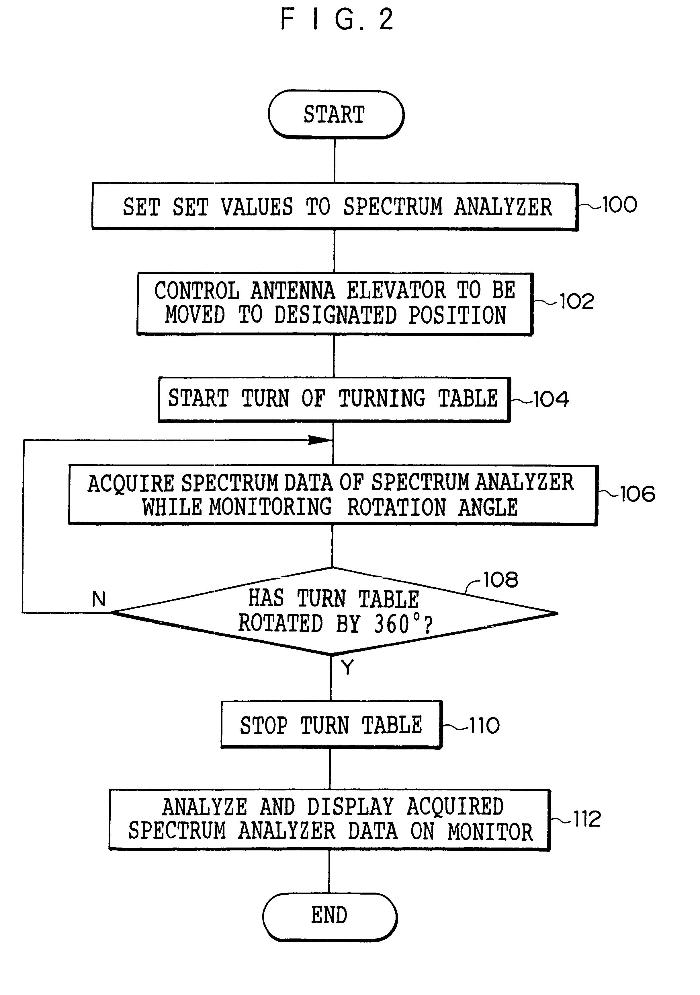
First, as already described in the first embodiment, electromagnetic noise radiated from the copying machine 26 is measured and the result is displayed on the monitor 34 according to the flow charts shown in FIGS. 2 and 5. Then, analysis target frequencies are selected from the point list 38 and moved to an analysis list (a different software) (in a step 600 shown in FIG. 12).

Next, the operator selects a point (frequency) to be analyzed from the analys...


PUM


Abstract

The object of the present invention is to provide an electromagnetic noise measurement apparatus, electromagnetic noise measurement method and recording medium capable of preventing erroneous measurement of electromagnetic noise and of enhancing measurement efficiency. An electromagnetic noise measurement apparatus includes a PC, a field intensity meter, a spectrum analyzer, a preamplifier, a controller, a printer and the like. The controller is connected to a turn table for turning an electromagnetic noise measurement target, e.g., a copying machine, and to an antenna elevator for elevating an antenna for measuring electromagnetic noise radiated from the copying machine. The controller controls the turn table and the antenna elevator according to command of the PC. The PC compares a QP value acquired by the field intensity meter with a peak level acquired by the spectrum analyzer, and displays an error message if the difference between the QP value and the peak level is large.

Description

1. Field of the InventionThe present invention relates to an electromagnetic noise measurement apparatus, an electromagnetic noise measurement method and a recording medium. More particularly, the present invention relates to an electromagnetic noise measurement apparatus and an electromagnetic noise measurement method for measuring electromagnetic noise radiated from electronic equipment, as well as a recording medium.2. Description of the Related ArtRecently, as electric equipment and electronic equipment spreads, electromagnetic interference becomes an object of social concern. To deal with this problem, a standard (VCCI or FCC) is set in each country. It is required to satisfy these standards when apparatuses are put on the market.To judge whether or not electric equipment or electronic equipment conforms to an EMI standard, it is necessary to measure electromagnetic noise radiated from the equipment and to check if a measurement value is below a standard value. The electromagne...

Claims


Application Information

Patent Timeline
Patent Type & Authority Patents(United States)
IPC IPC(8): G01R29/08
CPCG01R29/0871G01R29/0821
Inventor EBIZUKA, YASUOHIRATA, MASAYUKIYAMADA, KAZUNORISHINOZAKI, HARUOMATSUZAKI, TORUMORITA, TAKAJI
Owner FUJIFILM BUSINESS INNOVATION CORP
Learn More