Rocking motion immobilizer

a technology of immobilizer and rocking chair, which is applied in the direction of chairs, furniture parts, machine supports, etc., can solve the problems of not teaching the rocking chair immobilizer in the early art, presenting a threat of bodily injury to a child, and the rocking chair may be dangerous for elderly and handicapped persons, so as to achieve cost-effective and simple production

Inactive Publication Date: 2003-01-28
WILKENS JEREMY
View PDF15 Cites 10 Cited by
  • Summary
  • Abstract
  • Description
  • Claims
  • Application Information

AI Technical Summary

Benefits of technology

A further objective is to adapt the surface of the apparatus with an anti-skidding means for contact with a floor surface and thus enable the invented apparatus to remain firmly in place while immobilizing the rocking motion of the chair.
Still another objective is to provide a device which is made of s single piece of inexpensive plastic material, and thus is cost effective and simple to produce.

Problems solved by technology

However,: the prior art does not teach that a rocking motion immobilizer may be frictionally removably attached to the rocker and may be reinforced against sliding on the floor surface by a non-skid support.
Moreover, the prior art does not teach a rocking chair immobilizer which may be made at low cost, of plastic, in one piece, by an automated injection molding process.
While they are esthetically and functionally attractive, they may present a threat of bodily injury to a child who is trying to climb on the chair but falls backwards as a result of a front rocking motion.
The rocking chair may also be dangerous for elderly and handicapped persons when the chair is overturned by excessive back rocking movement under the heavy weight or unsecured movement of the elderly person's body.

Method used


Image

  • Rocking motion immobilizer
  • Rocking motion immobilizer
  • Rocking motion immobilizer

Examples


Embodiment Construction

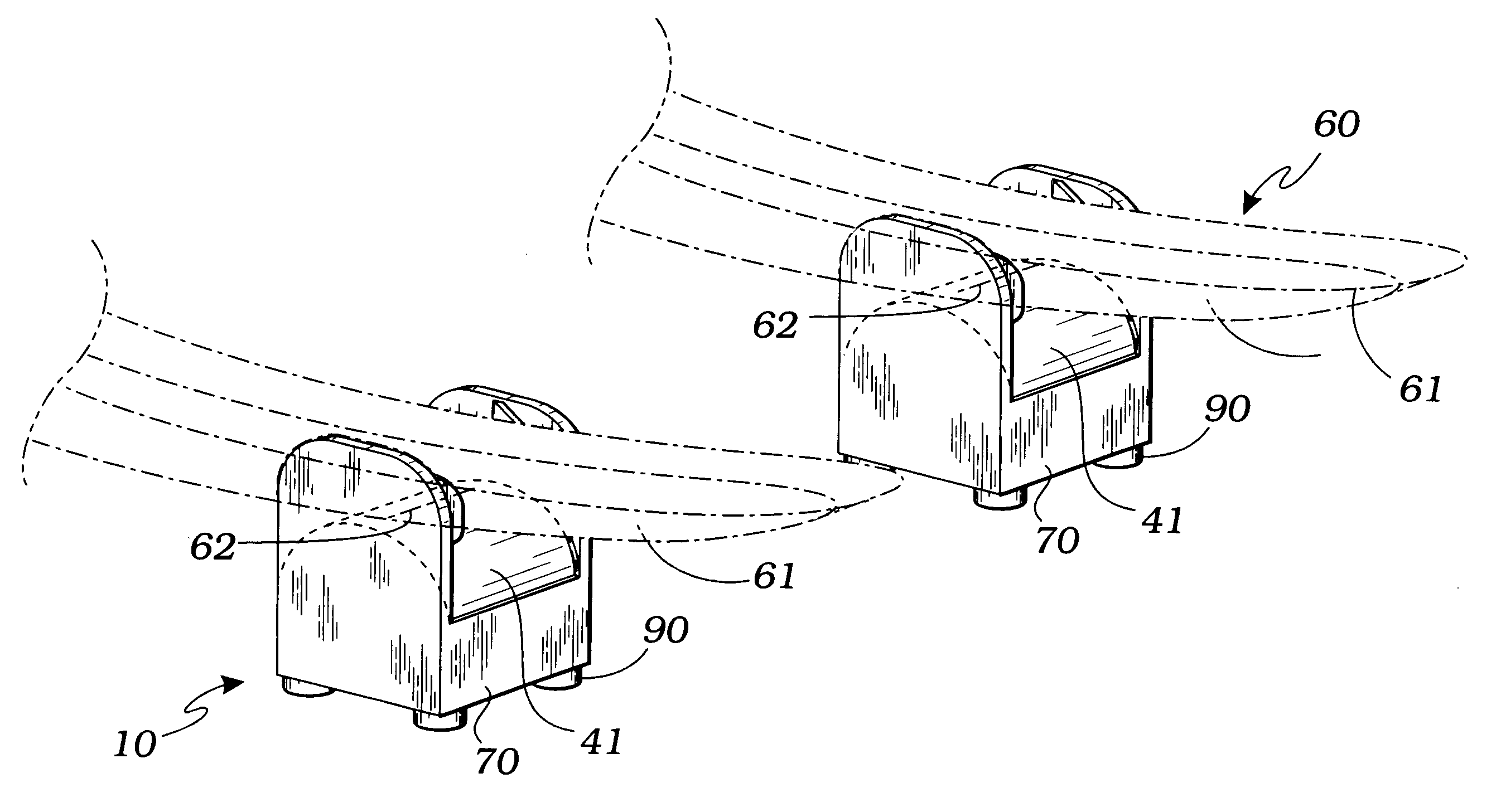
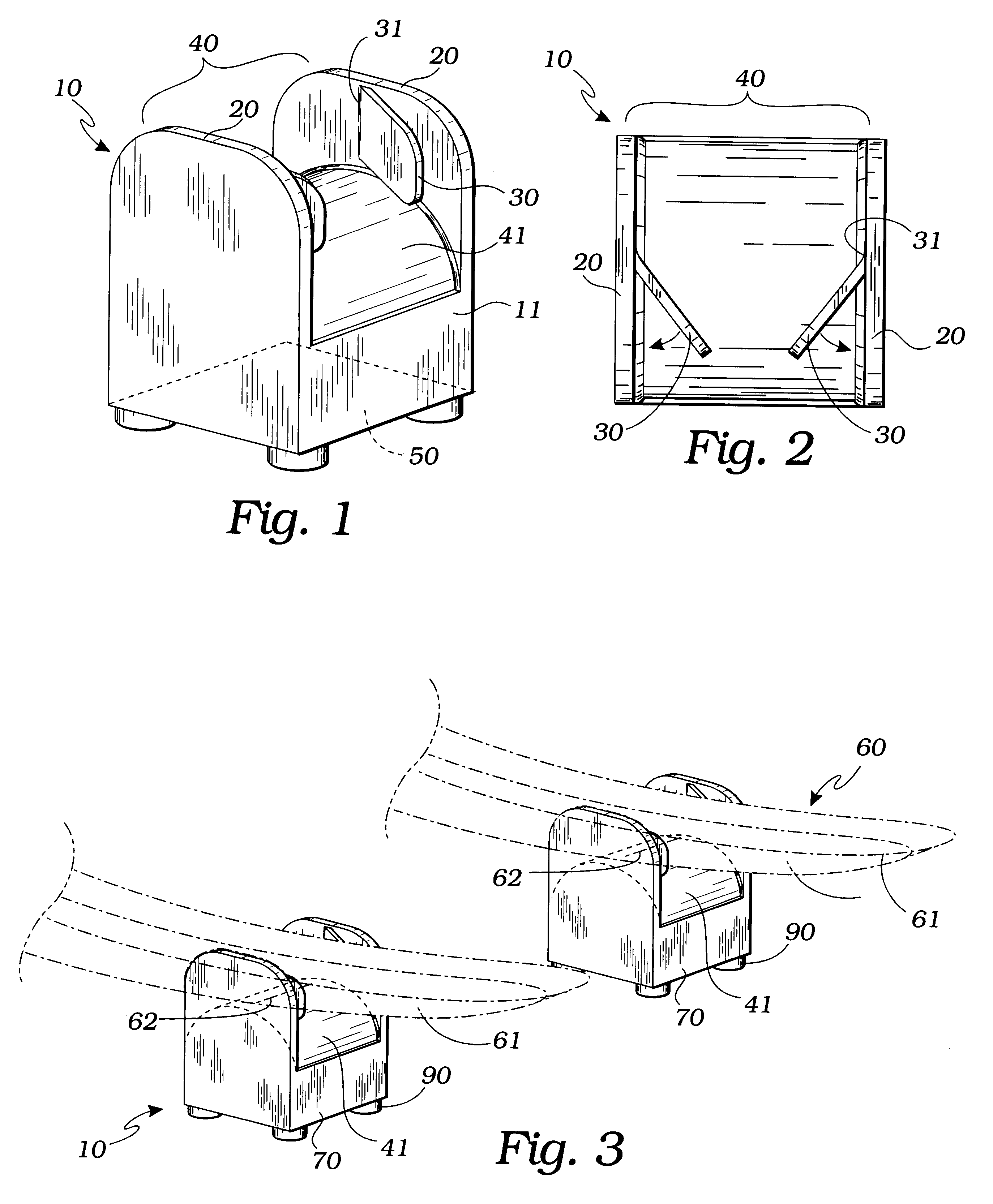
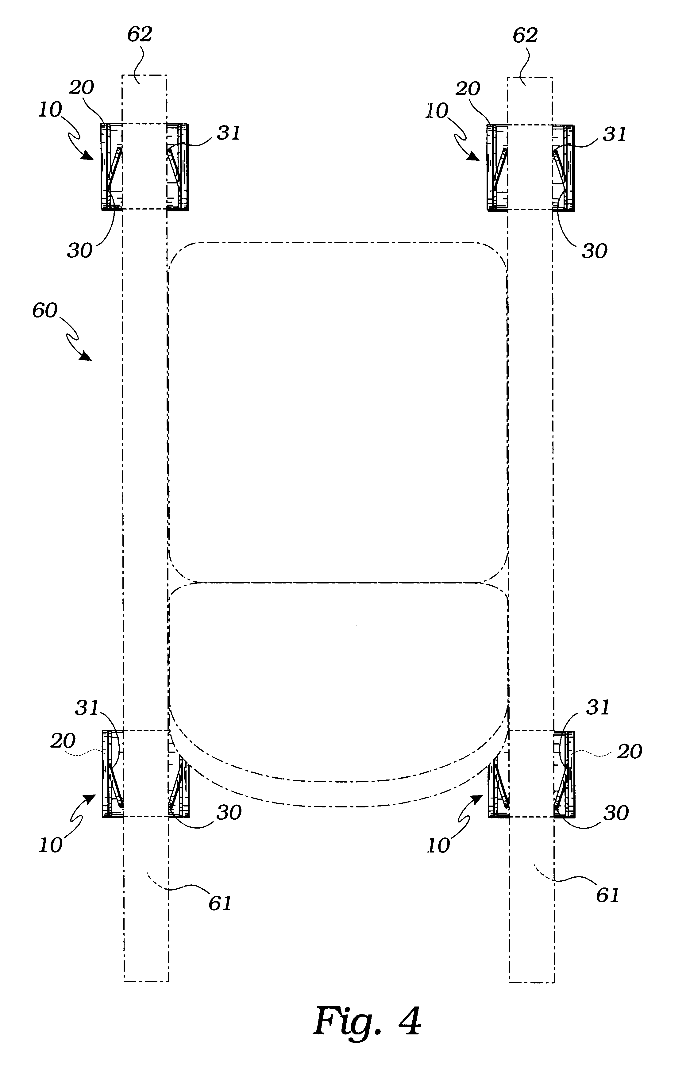
The above described drawing FIGS. 1 through 3 illustrate the invention, a rocking chair immobilizer 10, dimensioned to be inserted and fit between a floor surface 80 and a rocker 60 of a rocking chair to prevent the chair from a rocking movement. In a first preferred embodiment of the invention the apparatus 10 comprises a rigid block 11 which is molded of a plastic material, such as polyethylene, polypropylene, HDPE or other cost-effective plastic material. Alternatively, the rigid block 11 may be made of wood, metal or other structural material; however using a molding process is the most cost effective and least complicated way of producing the invention. The rigid block 11 preferably provides opposing and spaced apart integral rigid arms 20 which extend in essentially parallel juxtaposition therefrom so as to define a space 40 therebetween. Preferably, the arms 20 are made of the same plastic material as the block 11 and are of a thickness which enables rigidity. Additionally, t...


PUM


Abstract

The present invention provides an apparatus comprising a rigid block with two rigid arms such that there is at least one flexible flap extending from each of the arms in mutual convergent attitude and biased toward a center of the space between the rigid arms. The space between the rigid arms provides integral convexly curved surface such that it enables the invention to advantageously accept a downwardly facing surface of the rocker in line contact. The invented device, wedged between a rocker of a chair and a floor surface, receives the rocker in the space between the rigid arms, upon which the flexible flaps, having by construction bias sufficient to grip of the rocker, hold the invention on the rocker so that the chair is precluded from a rocking motion and thus is immobilized. Additionally, the apparatus' surface facing a floor surface is adapted with an anti-skidding device for contact with the floor. For partial immobilization, the invented device may be used on the front or back rocker to immobilize the front or back rocking motion, respectively. Alternatively, the apparatus may be used wherein two rigid blocks placed in opposing positions on the rocker of the rocking chair and in contact with the floor surface, thus rendering the rocking chair fully immobilized.

Description

1. FIELD OF THE INVENTIONThis invention relates generally to rocking chair immobilizers, and more particularly to an immobilizer with features adapted to grip a rocker of a rocking chair.2. DESCRIPTION OF RELATED ARTThe following art defines the present state of this field:Yehle, U.S. Pat. No. 594,311 describes attachments for baby-carriages having the combination of two rocker-frames provided with clips to engage the carriage-wheels, and joint or collapsible rod connections between said frames, substantially as described.Metzger, U.S. Pat. No. 1,400,564 describes a device embodying a supporting base having two members. One of the members constituting an upright, means pivotally connecting said members whereby the said upright may be caused to assume any desired angle with respect to a supporting surface and a sign holder flexibly connected with the upright and adapted to receive and removably hold a sign, said sign holder being independent of the pivot between the members and adapt...

Claims


Application Information

Patent Timeline
Patent Type & Authority Patents(United States)
IPC IPC(8): A47C3/029A47C3/03A47C3/02
CPCA47C3/029A47C7/002A47C3/03
Inventor WILKENS, JEREMY
Owner WILKENS JEREMY
Why Eureka
Try Eureka