Autonomous moving apparatus having obstacle avoidance function

a technology of autonomous moving and obstacle avoidance, which is applied in the direction of vehicle position/course/altitude control, using reradiation, instruments, etc., can solve the problems of increasing costs, unable to efficiently avoid obstacles both in direction and distance, and cannot clearly be recognized, so as to reduce power dissipation and facilitate avoiding obstacles efficiently

Inactive Publication Date: 2003-02-04
MATSUSHITA ELECTRIC WORKS LTD
View PDF11 Cites 35 Cited by
  • Summary
  • Abstract
  • Description
  • Claims
  • Application Information

AI Technical Summary

Benefits of technology

The obstacle detecting element guesses the position of an obstacle based on detection information from both the scan-type and non-scan-type sensors if the distance with respect to a specific configuration of the obstacle detected by the specific-configuration detecting element is smaller than a value set in the memory and, otherwise or if no specific configuration was detected, guesses the position of the obstacle based on only the detection information from the scan-type sensor. Thus, when the distance with respect to an object with a specific configuration is large or no specific configuration of object cannot be detected, only the scan-type sensor is used in detection, thus enabling avoiding the obstacle efficiently.
The obstacle detecting element activates the non-scan-type sensor when the specific-configuration detecting element provides a detection output. Thus, power dissipation can be reduced at the non-scan-type sensor.

Problems solved by technology

With only one sensor 5 alone, however, an obstacle 9, even if detected by it, cannot be decided on whether it is located at a position e or f. This means that the obstacle cannot clearly be recognized and so cannot be avoided efficiently both in direction and in distance.
Such an arrangement of many sensors, however, not only increases the costs but also needs complicated processing to eliminate interference between the sensors.
If an obstacle detecting element by use of the first optional supersonic or infrared sensor and that by use of the second optional radar device are only combined, collision with an obstacle can be avoided but the problem of an inefficiency inherent to the former detecting element cannot be avoided in avoiding an obstacle that can be detected by it.

Method used


Image

  • Autonomous moving apparatus having obstacle avoidance function
  • Autonomous moving apparatus having obstacle avoidance function
  • Autonomous moving apparatus having obstacle avoidance function

Examples


Embodiment Construction

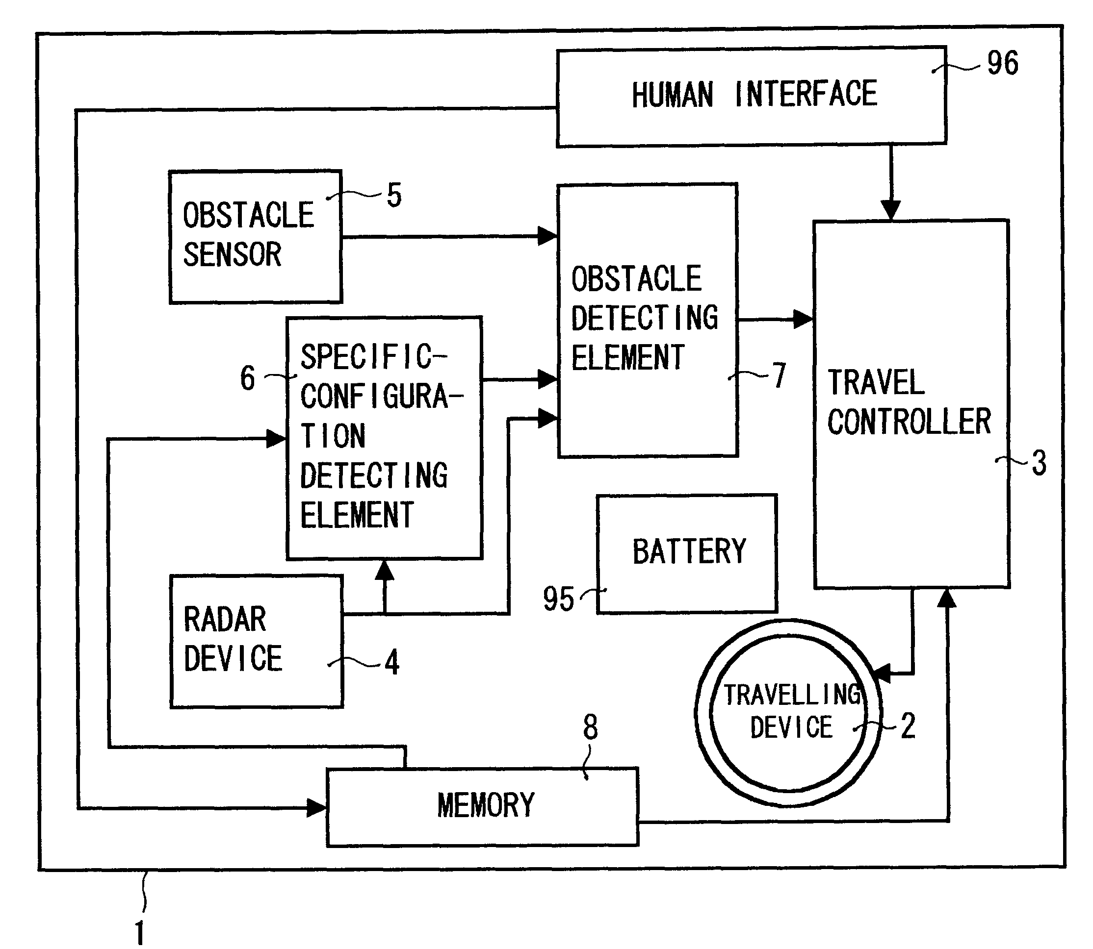
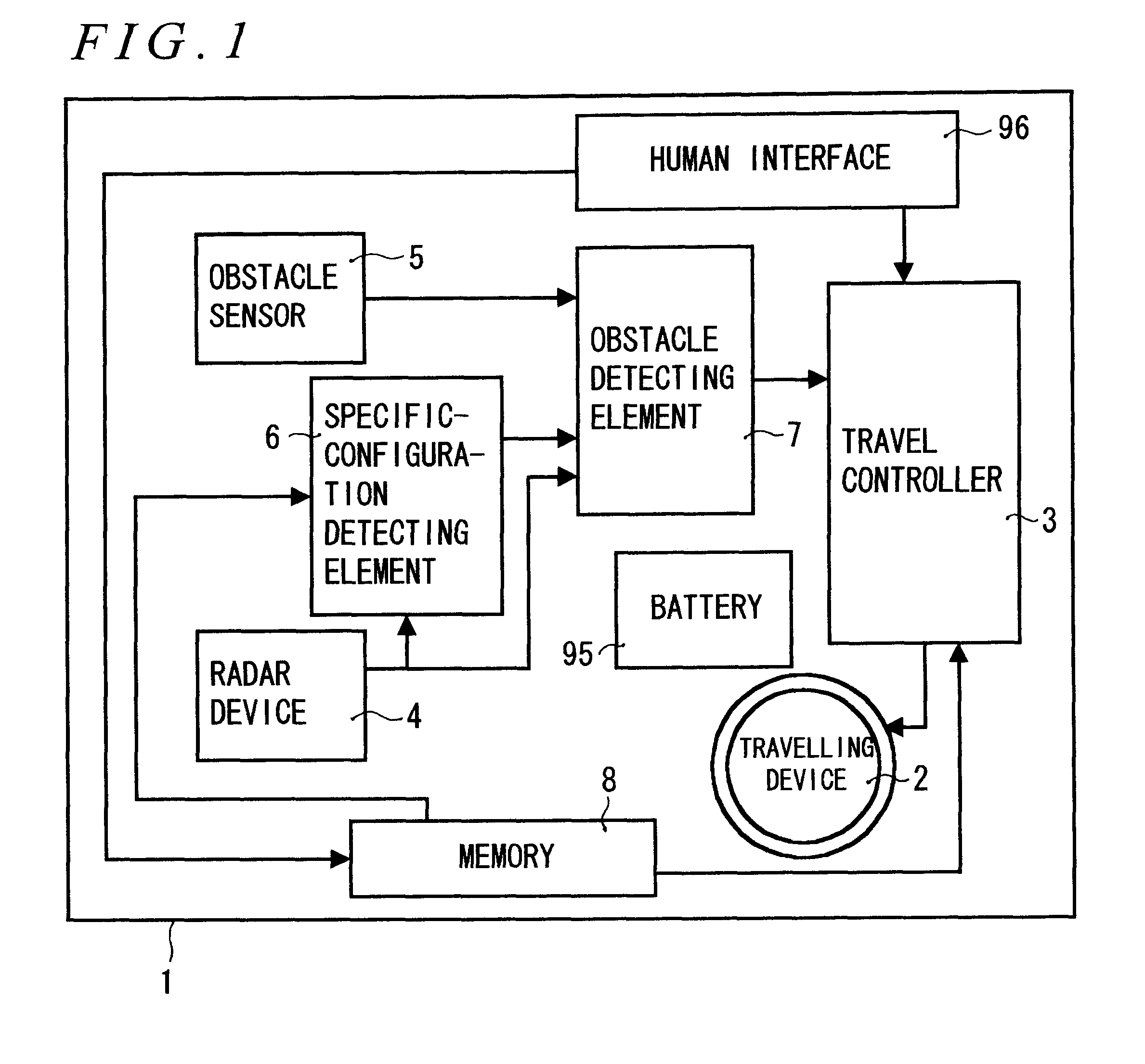
The following will describe one example of an embodiment of the invention. FIG. 1 is a block diagram for showing an autonomous moving apparatus 1 of the invention. The autonomous moving apparatus 1 includes a travelling device 2 capable of travelling and steering, a travel controller 3 for controlling the travelling device 2, a scan-type sensor (hereinafter called radar device) 4 comprised of a radar etc. for scanning a horizontal plane in a travelling direction of the travelling device 2 to thereby detect an obstacle, a non-scan-type sensor (hereinafter called obstacle sensor) 5 comprised of a supersonic or infrared sensor for detecting an obstacle in a space different from the scanning plane of the radar device 4, a specific-configuration detecting element 6, an obstacle detecting element 7, and a memory 8.

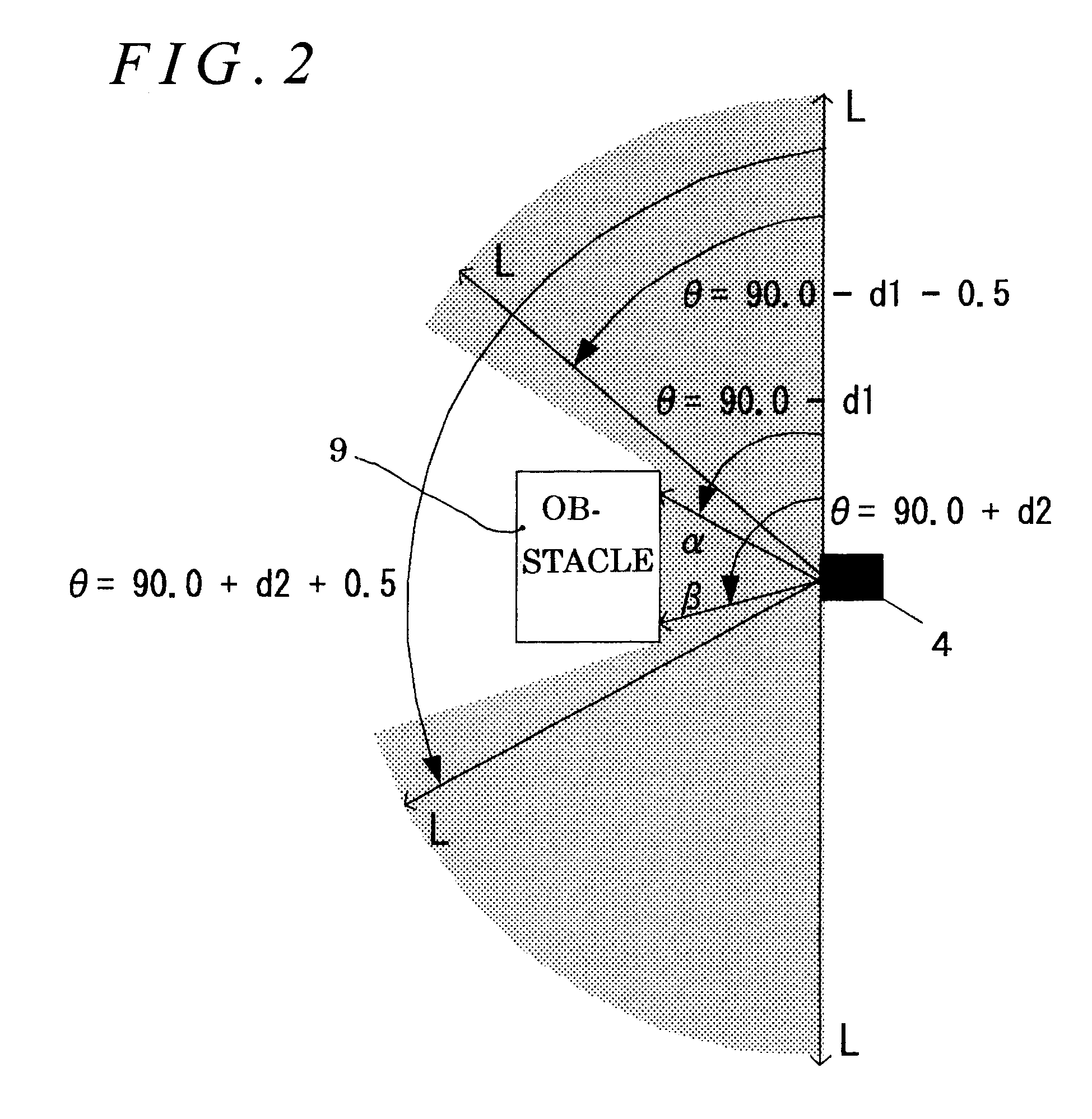
The specific-configuration detecting element 6 serves to detect a set specific configuration based on information obtained from the radar device 4 which scans a scanning plane. ...


PUM


Abstract

An autonomous moving apparatus moving to a destination while detecting and avoiding an obstacle includes a radar device for scanning a horizontal plane in its travelling direction to thereby detect a position of an obstacle and an obstacle sensor for detecting an obstacle in a space different from the scanning plane of the radar device. The apparatus moves to the destination under such control as to avoid the obstacle based on detection information from the radar device and the obstacle sensor from a detection output provided by a specific-configuration detecting element for detecting a present specific configuration from scanning information by the radar device. By providing such a specific-configuration detecting element that detects a specific configuration based on the scan information by the radar device that can accurately know about position information, it is possible to guess an obstacle having an upper structure, thus providing efficient avoidance.

Description

BACKGROUND OF THE INVENTIONThe invention relates to an autonomous moving apparatus performing required operations such as movement while detecting and avoiding an obstacle.There are available two methods of providing an autonomous moving apparatus with an obstacle detecting element for avoiding an obstacle: by using a supersonic or infrared sensor as the obstacle detecting element or by using as it a radar device for scanning a horizontal plane.To detect an obstacle with the former obstacle detecting element, that is, with a supersonic or infrared sensor, however, many sensors each having a small detection area need to be arranged in order to accurately detect the position of an obstacle in a wide detection area (see Japanese Unexamined Patent Publication No. 7-49381).As shown in FIG. 15(a), for example, in an autonomous moving apparatus 1 mounted with an obstacle sensor 5 utilizing a supersonic wave or an infrared ray and the sensor 5 having a wide detection area 50, a wide detecti...

Claims


Application Information

Patent Timeline
Patent Type & Authority Patents(United States)
IPC IPC(8): G01S15/00G01S17/93G01S17/00G01S17/02G01S15/93G01S17/87G05D1/02G01S15/88G01S15/931G01S17/86G01S17/931
CPCG01S15/931G01S17/023G01S17/87G05D1/0257G01S17/936G01S2015/939G05D1/0242G05D1/0255G01S17/86G01S17/931G01S15/88
Inventor SAKAI, TATSUOKITANO, YUKIHIKO
Owner MATSUSHITA ELECTRIC WORKS LTD
Why Eureka
Try Eureka