Apparatus, system, and method for simplifying annotations on a geometric surface

Inactive Publication Date: 2003-02-11
IBM CORP
View PDF8 Cites 13 Cited by
  • Summary
  • Abstract
  • Description
  • Claims
  • Application Information

AI Technical Summary

Benefits of technology

An object of this invention is an improved system and method to simplify the number of line segments used as annotations on a surface.
An object of this invention is an improved system and method to simplify the number of line s

Problems solved by technology

Texture mapping requires specialized graphics hardware for adequate performance during viewing, and that hardware is not currently guaranteed to be present on all computers.
When multiple images are used to represent the annotations of the model at the same time, differences in rendering parameters between images may result in a discontinuity where the images border each other and this discontinuity can stand out as a disturbing artifact.
Annotations that do not appear seamless may be hard to interpret because the eye is drawn to the abrupt changes in surface characteristics rather than the actual features on the surface.
Consequently, the annotations may become an ineffective means for conveying the additional information to the viewer.
Texture maps also suffer from blurring and pixelization at high magnification.
If the vie

Method used


Image

  • Apparatus, system, and method for simplifying annotations on a geometric surface
  • Apparatus, system, and method for simplifying annotations on a geometric surface
  • Apparatus, system, and method for simplifying annotations on a geometric surface

Examples


Embodiment Construction

.

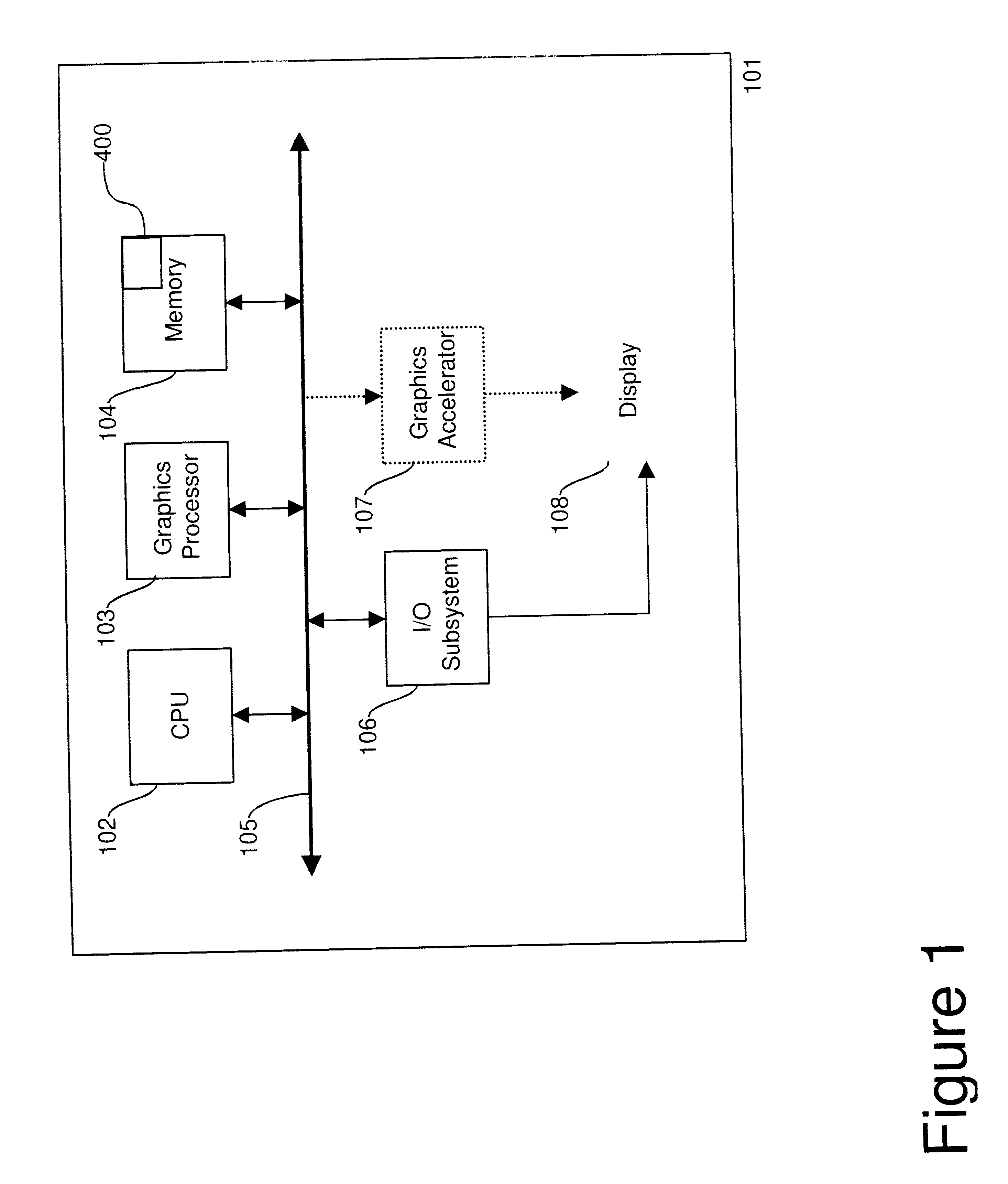
Referring now to the drawings, and more particularly, FIG. 1 is a block diagram of a preferred embodiment geometric modeling system 101 that includes a memory 104 where one or a plurality of geometric models are stored. One or more Central Processing Units (CPU) 102 access the model via the internal bus 105 and assist a graphics processor 103 in rendering the image and conveying it via the I / O subsystem 106 and the graphics accelerator 107 to the display 108. Optionally, the internal bus 105 may be connected to a network interface to transmit the geometric models across a network to remote modeling systems. These components are all well-known. A novel annotation simplification process 400, described in more detail in FIG. 4, is executed by one or more of the CPUs.

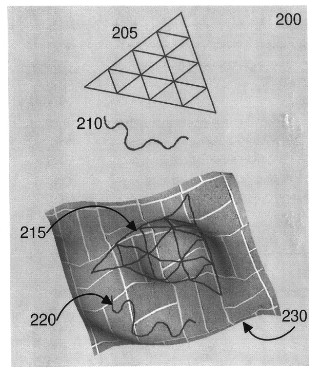
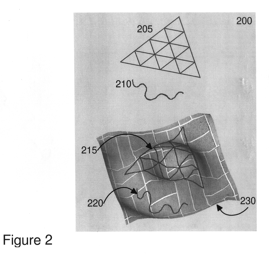
FIG. 2 shows an example 200 of annotations on the surface of a model 230. The geometry of the model defines the actual shape of the surface. In this example, the geometry represents an undulating surface. The attributes fo...


PUM


Abstract

A computer system and method for simplifying annotations on a surface includes a tolerance process creates a tolerance window lying in a plane and centered on the query point at the end of a test edge and perpendicular to the test edge. The tolerance window is defined by a first tolerance that specifies an amount of first error measured by the distance from a simplified path to an original path in the plane tangent to the surface, and a second tolerance that specifies an amount of second error measure by the distance from the simplified path to the original path in the plane perpendicular to the surface. The original path is a set of original edges on the surface. A point projection process that projects a second end point of one or more second edges onto the plane of the tolerance window. The second edges has the query point also as an end point where the projection of the second end points are projected points. An invalidation process marks an edge as "invalid" and removes it both from the list of simplifiable edges and the final list of simplified edges. A selection process selects one of the second end points that has a projected point within the plane containing the tolerance window, deletes the query point, and connects the origin point to the respective second end point, to create a new edge that replaces the test edge and respective second edges in the set of original edges to create the simplified path.

Description

This invention relates to the field of geometric modeling. More specifically, the invention relates to computation, visualization and / or annotation of geometric models.In CAD / CAM and other areas, one needs to view and interact with 3D models obtained from a local machine or a remote server. These 3D models contain both geometry to define their shapes and surface features, such as color and annotations. Some annotations correspond to a two-dimensional figure mapped onto the surface of the geometric model. In order to improve performance, there is also a growing need to represent these complex three-dimensional models by simplified versions that are less expensive to store in memory on a computer, faster to transmit across a network from one computer to another computer, and faster to render on a computer. To address this, many techniques have been developed to simplify a model with minimal loss in perceived quality. See, for example, U.S. Pat. No. 5,929,860 or the article "Surface Si...

Claims


Application Information

Patent Timeline
IPC IPC(8): G06T17/40G06T15/04G06F17/50G06T17/00G06T19/00
CPCG06T19/00G06T17/205G06T2219/012G06T2219/004
Inventor SUITS, FRANKKLOSOWSKI, JAMES T.HORN, WILLIAM P.LECINA, GERARD
Owner IBM CORP
Why Eureka
Try Eureka