Spot beam location method and apparatus

a technology of spot beam and location method, applied in the field of spot beam location method and apparatus, can solve the problems of high power consumption, waste of frequency spectrum, and complex circuitry

Inactive Publication Date: 2003-02-18
INMARSAT TWO CO
View PDF20 Cites 34 Cited by
  • Summary
  • Abstract
  • Description
  • Claims
  • Application Information

AI Technical Summary

Benefits of technology

Preferably, the satellite is able to project a wide beam which substantially covers the area of all the spot beams, and information is broadcast in the wide beam which identifies which signalling channels may be used. The terrestrial terminals receive this information and transmit signals on the signalling channel or channels i...

Problems solved by technology

However, a problem associated with satellites having multiple spot beams is that, in order to communicate with a transceiver, it is necessary to know in which spot beam the transceiver is located, so that an appropriate communications channel can beassigned to the transceiver in that spot beam.
This problem arises both for geostationary satellites, because the transceivers may move between and during calls, and for non-geostationary satellites, ...

Method used


Image

  • Spot beam location method and apparatus
  • Spot beam location method and apparatus
  • Spot beam location method and apparatus

Examples


first embodiment

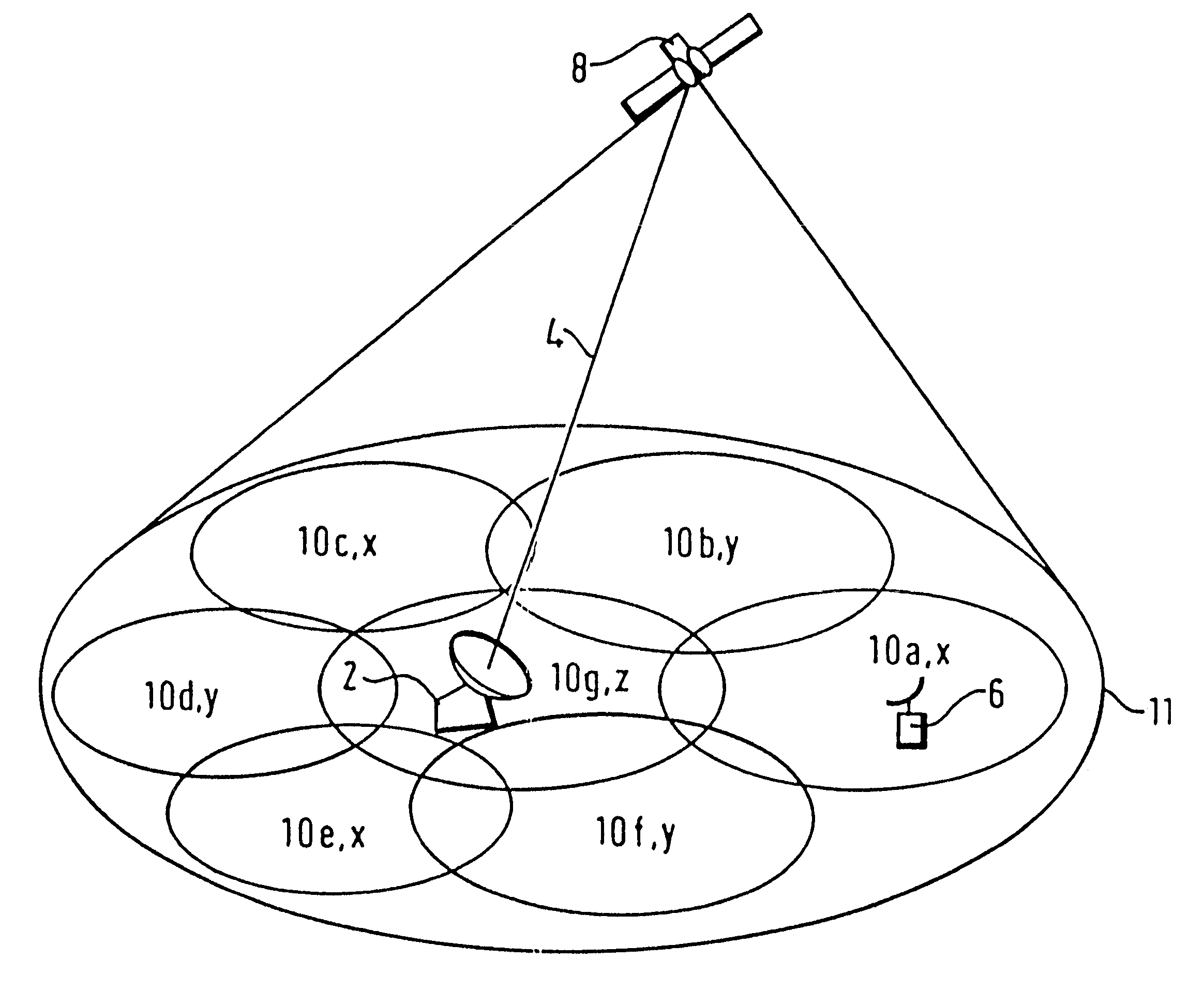
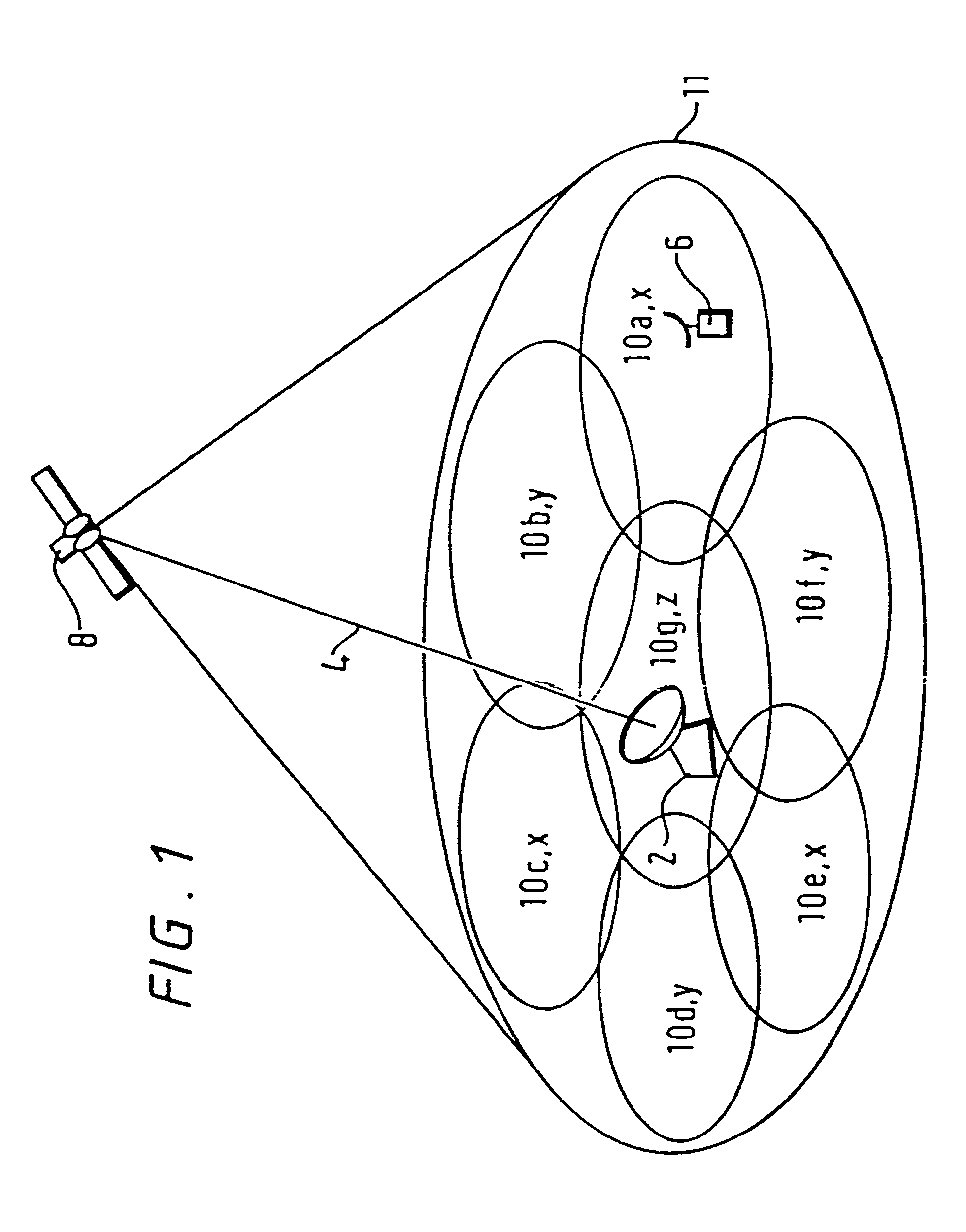
The first embodiment relies on the ability of the satellite 8 to receive the same signalling channel in all of the spot beams. However, conventional satellites are designed not to receive the same frequency channels in overlapping spot beams. Instead, the spot beams are divided into three or more groups, labelled as X, Y and Z in FIG. 1. All the spot beams in the same group are allocated the same frequency channels, but because the spot beams within each group do not overlap, there is no transmit or receive interference in these channels.

second embodiment

the present invention is similar to the first embodiment, but is applied to circumstances when the satellite 8 divides spot beams into groups as described above. In this embodiment, a different return signalling channel is allocated to each of the groups X, Y and Z. For example, the satellite 8 receives a first signalling channel at frequency f.sub.1 from all the group X spot beams, a second signalling channel at frequency f.sub.2 from all the group Y spot beams, and a third signalling channel at frequency f.sub.3 from all the group Z spot beams. Group X comprises Spot beams 10a, 10c and 10e; the first signalling channel received from spot beam 10a is retransmitted at frequency f.sub.1 in the feeder link 4, the first signalling channel received from spot beam 10c is retransmitted at frequency f.sub.2 and the first signalling channel received from spot beam 10e is retransmitted at frequency f.sub.3. Likewise, the second signalling channel received by spot beams 10b, 10d and 10f is re...

third embodiment

the present invention is applied to a terrestrial cellular communications system assisted by information broadcast from a satellite. As shown in FIG. 10, the terrestrial cellular system comprises a control centre 72 connected co a plurality of base stations 70a to 70e, each of which is able to transmit and receive signals over an area which defines a cell. A communications link is established between a mobile terminal 76 and the control centre 72 through the base station 70d which defines the cell into which the mobile terminal 76 falls. A satellite 74 broadcasts signalling channel information over an area 78 which encompasses all of the cells. Each co the base stations 70 is arranged to receive the same signalling channel. The mobile terminal 76 receives information broadcast by the satellite 74 which indicates the signalling channel, and transmits a signal on the signalling channel, which may be received by any of the base stations 70. The control censure 72 compares the strength ...


PUM


Abstract

A mobile terminal (6) communicates via a satellite (8), which projects a number of overlapping spot beams (10), with a fixed earth station (2). To determine which spot beam (10) is to be used for communication, the mobile terminal signals in a common signalling channel which is simultaneously received by all, or a subgroup of, the spot beams (10). The satellite (8) retransmits to the fixed earth station (2) in separate channels the signal as received by each of the spot beams (10) which are able to receive the common signalling channel. The relative strengths of the signal as received in the different spot beams (10) are compared at the fixed earth station and a communications channel is assigned to the mobile terminal in one of the spot beams (10), selected according to the comparison of signal strengths.

Description

The present invention relates to a method and apparatus for radio frequency communications, and in particular to a method and apparatus for selecting a spot beam for communication with a radio frequency transceiver in a satellite communications system in which a satellite projects a plurality of overlapping spot beams over an area of the earth's surface. Each spot beam carries a plurality of communication channels, which are re-used in spot beams which do not overlap. In this way, the communications traffic capacity of a satellite communication system is greatly increased over satellite systems which only use a single beam per satellite.However, a problem associated with satellites having multiple spot beams is that, in order to communicate with a transceiver, it is necessary to know in which spot beam the transceiver is located, so that an appropriate communications channel can beassigned to the transceiver in that spot beam. This problem arises both for geostationary satellites, b...

Claims


Application Information

Patent Timeline
IPC IPC(8): H04B7/204H04B7/185H04B7/15
CPCH04B7/2041H04B7/1855
Inventor FEBVRE, PAULPHILLIPS, KEVIN
Owner INMARSAT TWO CO
Why Eureka
Try Eureka