

Damped crash attenuator
a technology of attenuator and crash, which is applied in the direction of shock absorber, elastic damper, way, etc., can solve the problems of increasing the severity of the crash, system not adapting, and often confused structure and energy absorption functions, etc., to achieve large energy dissipation force, low energy absorption level, and variable energy dissipation force
Inactive Publication Date: 2003-02-25
AMERICAN VEHICULAR SCI
View PDF39 Cites 97 Cited by
- Summary
- Abstract
- Description
- Claims
- Application Information
AI Technical Summary
Benefits of technology
It is another object of the present invention to provide a new and improved crash attenuator for mounting on a truck of stationary structure which is reusable.
A key advantage of the attenuators of this invention is that they are for the most part collapsible to a length substantially shorter than their expanded or deployed length. In some cases, the collapsed length is less than about 25% of the expanded length. This permits the attenuator to be easily stored, shipped and transported to the work site. To decrease their length, current TMAs are rotated into a vertical position during transportation to the work site. This not only requires expensive hydraulic apparatus to be mounted onto the vehicle to provide the power to rotate the TMA to and from the vertical position but it also limits the length of the TMA and thus the degree of protection afforded by the device.
Problems solved by technology
No TMA on the market today satisfactorily meets all of these requirements.
In fact, the prior art inventions have frequently confused the functions of structure and energy absorption.
Since the orifices are fixed, the system will not adjust to vehicle impacts of varying kinetic energy to provide a constant deceleration.
Also, since the device is substantially composed of such cylinders, it is heavy if used as a TMA.
This increases the severity of the crash and thus the potential for injury to the construction crew and the vehicle occupants.
The system is not reusable and does not adjust to impacting vehicles having different kinetic energies.
This system is reusable but does not adjust to impacting vehicles having different kinetic energies.
By having the function of an ever increasing force with displacement, it is particularly inefficient in decelerating a vehicle where a constant force is desired.
This system is not reusable and does not adjust to impacting vehicles having different kinetic energies.
By having the function on an ever increasing force with displacement, it is particularly inefficient in decelerating a vehicle where a constant force is desired.
It also suffers from the same limitations as Krage et al.
The bending of metal is the energy absorption mechanism and thus has the same limitations as Krage et al.
The system is not reusable and does not adjust to the kinetic energy of the impacting vehicle.
Accordingly, none of the prior art patents mentioned above discloses a TMA having the sought after properties and thus, a critical need exists for such a device.
A central issue is that since prior art TMAs are not optimally designed, they must be made very long in order to handle both low and high mass vehicles at high speed.
This makes the devices expensive, difficult to maneuver and less than optimum as a life saving device.
Method used
View moreImage
Smart ImageViewing Examples

Examples
Embodiment Construction
With the input W.sub.T =16000 lbs, W=4400 lbs, A=24 square feet (3 feet by 8 feet), L=10 x.sub.0 =62 mph, .mu.=0.7, p.sub.a =14.7 psia, T.sub.a =68 F, C.sub.D =0.6, .gamma.=1.4, R=1716.5 fps.sup.2 / R,
P.sub.1 =17.94 psia Equation (9)
X.sub.1 =1.33 feet Equation (10)
x.sub.1 =61.6 mph Equation (11)
x.sub.2 -x.sub.T2 =4.41 feet Equation (15)
p.sub.2 =33.2 psia Equation (13)
x.sub.2 -x.sub.T2 =54.6 mph Equation (14)
T.sub.2 =206 F Equation (17)
A.sub.o,max =4.37 square feet Equation (20)
X.sub.T =8.9 feet Equation (21)
Login to View More PUM
 Abstract
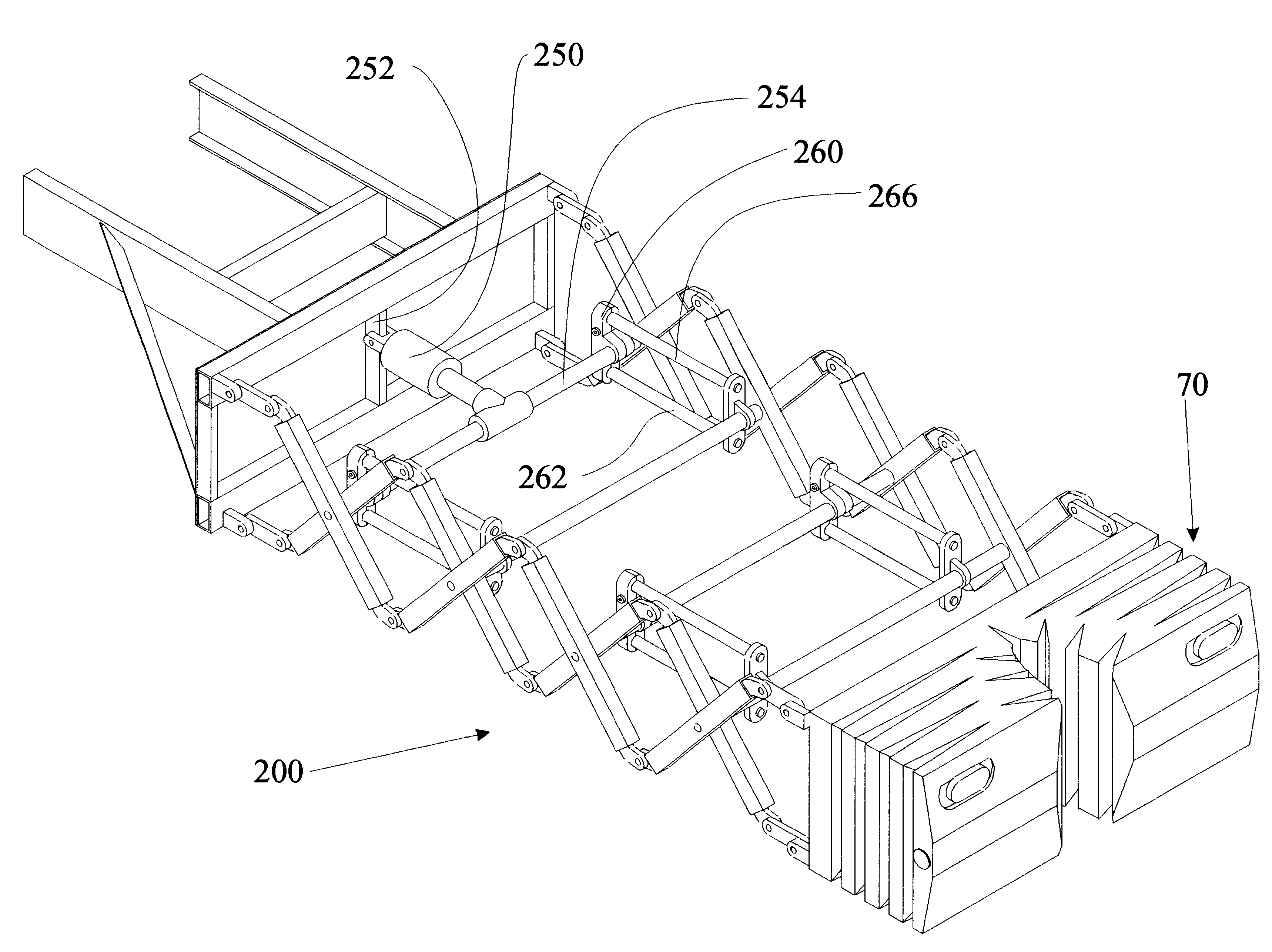
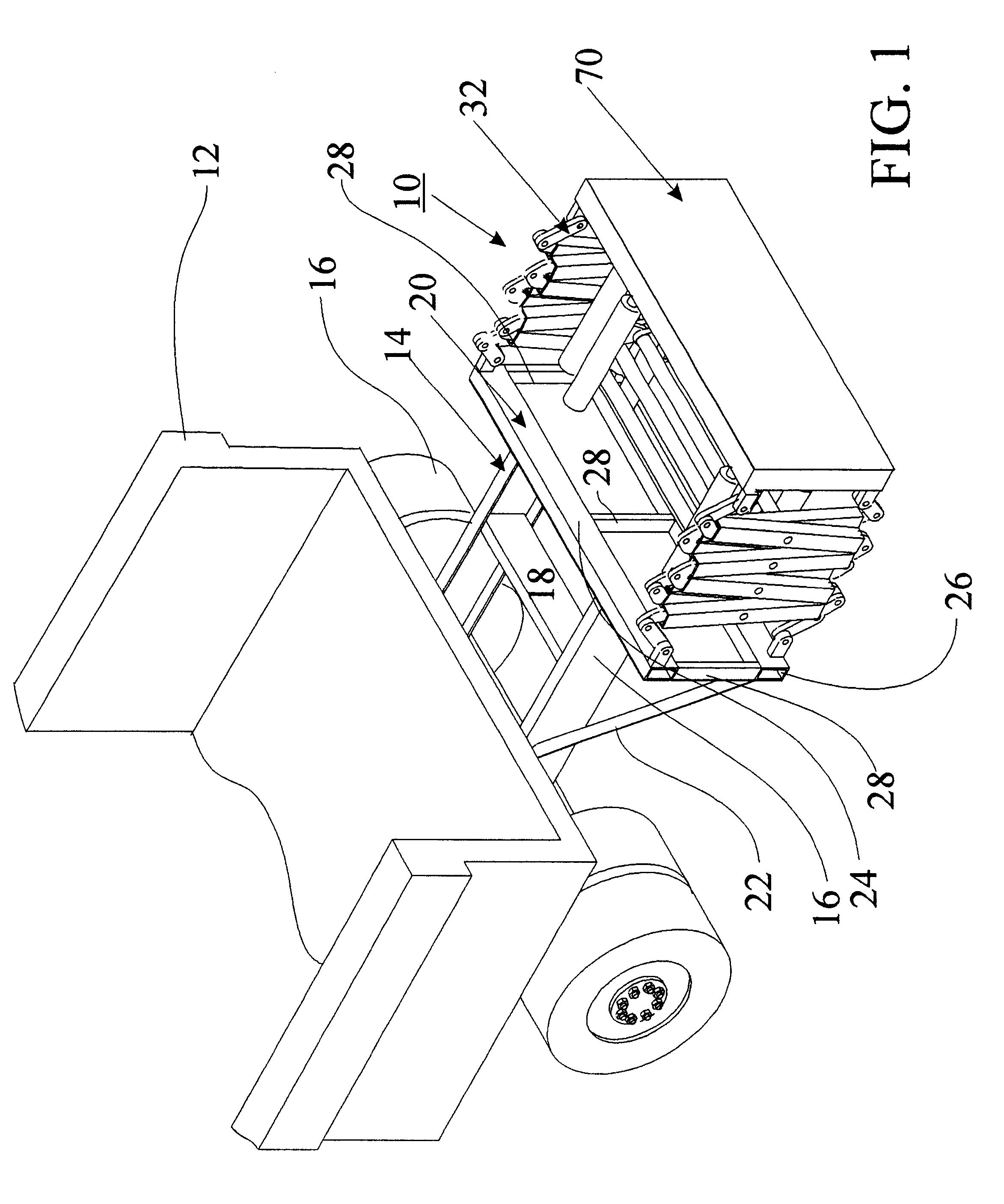
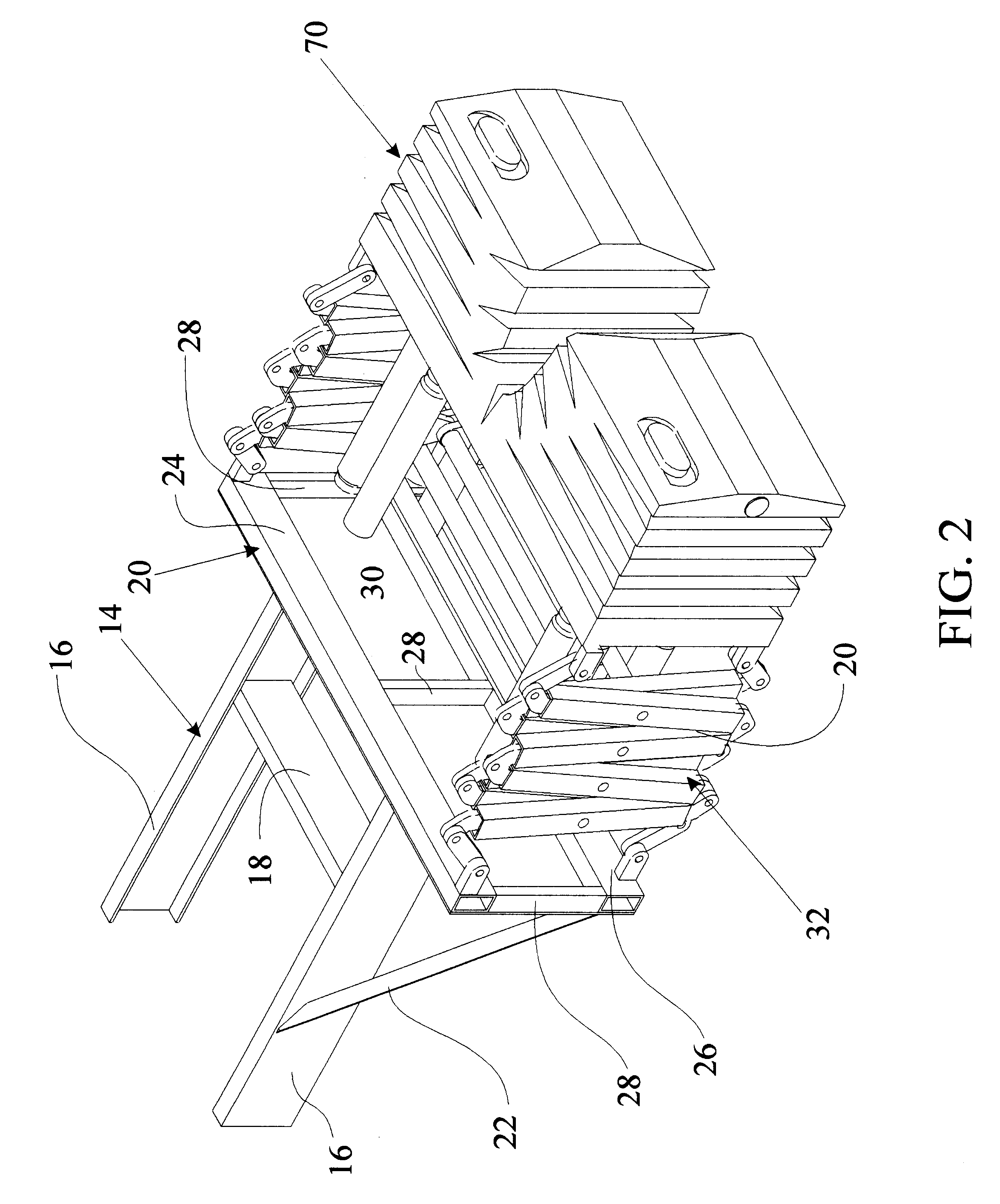
Crash attenuator for protecting a truck or stationary structure from damage resulting from impact of an object including a frame mountable to the structure, a bumper having an impact-receiving face adapted to receive an impact from the object, a movable displacement structure interposed between the frame and bumper and having a first position in which the bumper is relatively distant from the frame and a second position in which the bumper is relatively proximate to the frame, and an energy dissipation system coupled to the displacement structure for dissipating impact energy of the object received by the bumper which causes the displacement structure to be moved from the first position toward the second position. The energy dissipation system includes one or more deformable members which deform upon movement of the displacement structure from the first position toward the second position with such deformation causing dissipation of impact energy.
Description
The present invention relates in general to crash attenuators, and more particularly to medium-damped crash attenuators that use the flow of a medium such as a liquid or gas to dissipate the energy of an object such as a vehicle impacting the crash attenuator. It also relates in some cases to attenuators which use the controlled deformation of metal to absorb energy and thus damp the motion of the attenuator. Still more particularly, the invention relates to attenuators enabling active control of the rate of energy dissipation thereof to better control the deceleration of vehicles impacting the attenuator having widely varying kinetic energy.The present invention also relates to method for protecting fixed structures from damage caused by the impact of objects such as vehicles, for example, structures situated alongside highways.Many commercial products exist and numerous patents have been issued directed to the design and construction of impact attenuators or barriers to control th...
Claims
Login to View More Application Information
Patent Timeline
 Patent Type & AuthorityPatents(United States)
IPC IPC(8): B60R19/00E01F9/012E01F9/011E01F15/00E01F15/14F16F7/12F16F9/02F16F9/04B60R21/01B60R19/40B60R19/24B60R19/18B60R19/20B60R21/0134B60R21/0136
CPCB60R19/00F16F9/0472E01F9/0126E01F15/146E01F15/148F16F7/121B60R19/20B60R19/40B60R21/0134B60R21/0136B60R2019/007B60R2019/005E01F9/662
InventorBREED, DAVID S.
OwnerAMERICAN VEHICULAR SCI