Method and apparatus for producing a precise joint between two cover materials for a trim component

a technology of cover materials and trim components, applied in the direction of rigid containers, superstructure subunits, monocoque constructions, etc., can solve the problems of increased costs, higher rejection rate, and increased likelihood of defective parts

Inactive Publication Date: 2003-02-25
HERBERT OLBRICH
View PDF14 Cites 34 Cited by
  • Summary
  • Abstract
  • Description
  • Claims
  • Application Information

AI Technical Summary

Benefits of technology

By pinching the substrate in this manner, while pressing down from above with a tucking blade, and continuing and completing the pinching as the tucking blade is removed, it is ensured that the valley is pinched closed without leaving any gap or space resulting from the width or thickness of the tucking blade. The pinching securely adhesively fixes the bordering edges of the two different cover sheets onto the substrate in the valley, due to the tacky hot-melt adhesive effect of the hot substrate sheet, so that it is unnecessary to splice or bond the bordering edges to each other.
Since the pinching gap is initially much wider than the finished pinched valley, the degree of precision required for aligning or registering the junction line of the two different cover sheets over the pinching gap is significantly reduced. Namely, it is simply necessary to align the junction of the two cover sheets with the initially wide open gap in the molding tools used for forming the pinched valley, and when this gap is closed or pinched, the finished pinched valley is much narrower than the originally provide gap. Thus, the wider width of the initially open gap contributes to a larger tolerance for positioning the junction line of the two cover sheets, while the narrower closed gap defines the width of the finished valley pinching the cover sheet bordering edges therein.
Moreover, the depth of the pinching gap also contributes to the tolerance range for ultimately hiding the junction line of the two different cover sheet materials. By making the gap as deep and as wide as required in the initial open state of the molding tools, it is simple to provide a large tolerance for the proper positioning of the two different cover sheets onto the substrate and then positioning the substrate onto the mold, while still ensuring that the finished trim component will have a completely closed or pinched valley, with the junction of the two different cover sheets completely hidden within this valley. The resulting valley has a clean and crisp closed appearance, because the inner width of the substrate valley is not greater than the sum of the thicknesses of the two cover sheets overlapped and received in the pinched valley.
In view of the above, the present invention provides an improved method and apparatus in comparison to the above referenced parent application, whereby this improved method and apparatus avoid the differential lateral slipping of the cover sheet materials relative to the intended junction line within the pinched valley of the substrate. This is achieved in general terms by positively holding the substrate and the two cover sheets directly along the junction line before and during the operation of pushing the cover sheet edges into the valley of the substrate and then pinching closed this valley. The present method and apparatus positively enforce the junction line of the two cover sheets to become a fixed reference line, relative to which all slipping or stretching will take place. By defining the fixed reference line along the junction line in this manner, the respectively required degree of slipping will take place at the various respective locations of the slip frame without allowing the junction line to shift laterally for compensating different tensions or the like. For this reason, it becomes possible to precisely position and pinch the junction line between two cover materials in a pinched valley of a substrate, even if this pinched valley of the substrate has a complex curved contour in two dimensions or three dimensions.

Problems solved by technology

The preliminary process of splicing together the two different cover materials involves extra processing and handling steps, which translates into increased costs and a greater likelihood of defective parts leading to a higher reject rate.
Furthermore, the application of a trim strip to hide the splice line on the finished door panel, dashboard or the like requires extra steps and extra materials, which again lead to higher costs and higher defect rates.
It has been found in practice that this high degree of precision cannot be reliably attained, and as a result, the splice line is left at least partially visible in the finished trim component, i.e. the splice line protrudes out of the groove in the substrate or protrudes from under the splice trim strip.
This leads to an unacceptably high reject rate of the finished trim components.
After the tucking blade is retracted, however, a gap necessarily remains where the tucking blade had been pressed in.
In any event, the result in the finished trim component has been unsatisfactory, because of the above mentioned defects in alignment of the splice line with the groove, but also because of the width of the conventional groove, which does not have a "closed" and "crisp" appearance.
Namely, it is sometimes difficult to ensure that the junction between the two cover sheets remains precisely aligned in the valley of the substrate, even considering the range of tolerance that is afforded by this pinched valley as described above.
Particularly, in practice it has been found that the two cover sheet materials adhered onto the substrate very often undergo differential slipping or differential stretching as the tucking blade of the upper mold section pushes the junction line of the two cover sheets into the pinching gap in the pinching stamp of the lower mold section.
As a result, in practice, it has often been found that the junction line unintendedly slips laterally out of the pinching gap as the tucking blade pushes it down into the pinching gap.
The result is unsatisfactory, so that the affected pieces must be rejected.
However, any slight variations in the material characteristics of the two cover sheets, the process temperatures, the dimensions of the cover sheets, or the like, will again cause an unintended lateral slipping of the junction line relative to the valley in the substrate.
It would be impractical and economically prohibitive to require mechanical readjustment or calibration of the slip frame tension on an ongoing or often-repeated basis.

Method used


Image

  • Method and apparatus for producing a precise joint between two cover materials for a trim component
  • Method and apparatus for producing a precise joint between two cover materials for a trim component
  • Method and apparatus for producing a precise joint between two cover materials for a trim component

Examples


Embodiment Construction

The original invention, which is the subject matter of the above referenced parent application Ser. No. 09 / 176,356, now U.S. Pat. No. 6,212,157, will first be described in connection with FIGS. 1 to 4. An understanding thereof is essential to an understanding of the present further improved method and apparatus of the present Continuation-In-Part application, because the present improved method and apparatus incorporate all of the features of the original invention, and further incorporate certain improvements, which will be additionally described in connection with FIGS. 5 to 10 below.

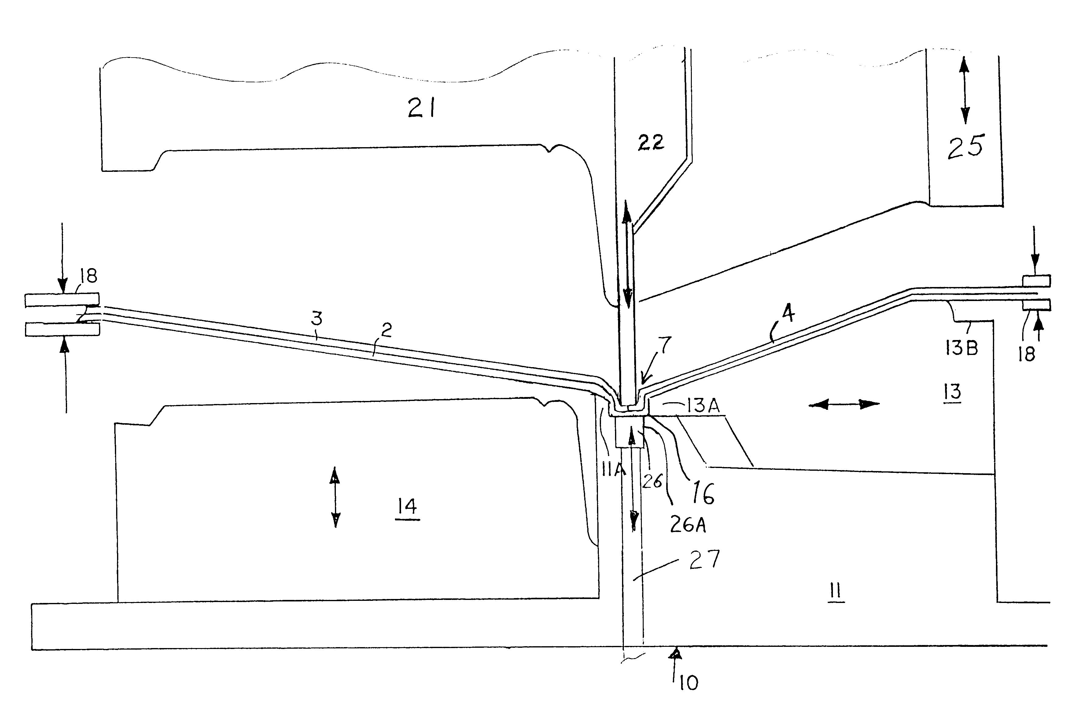
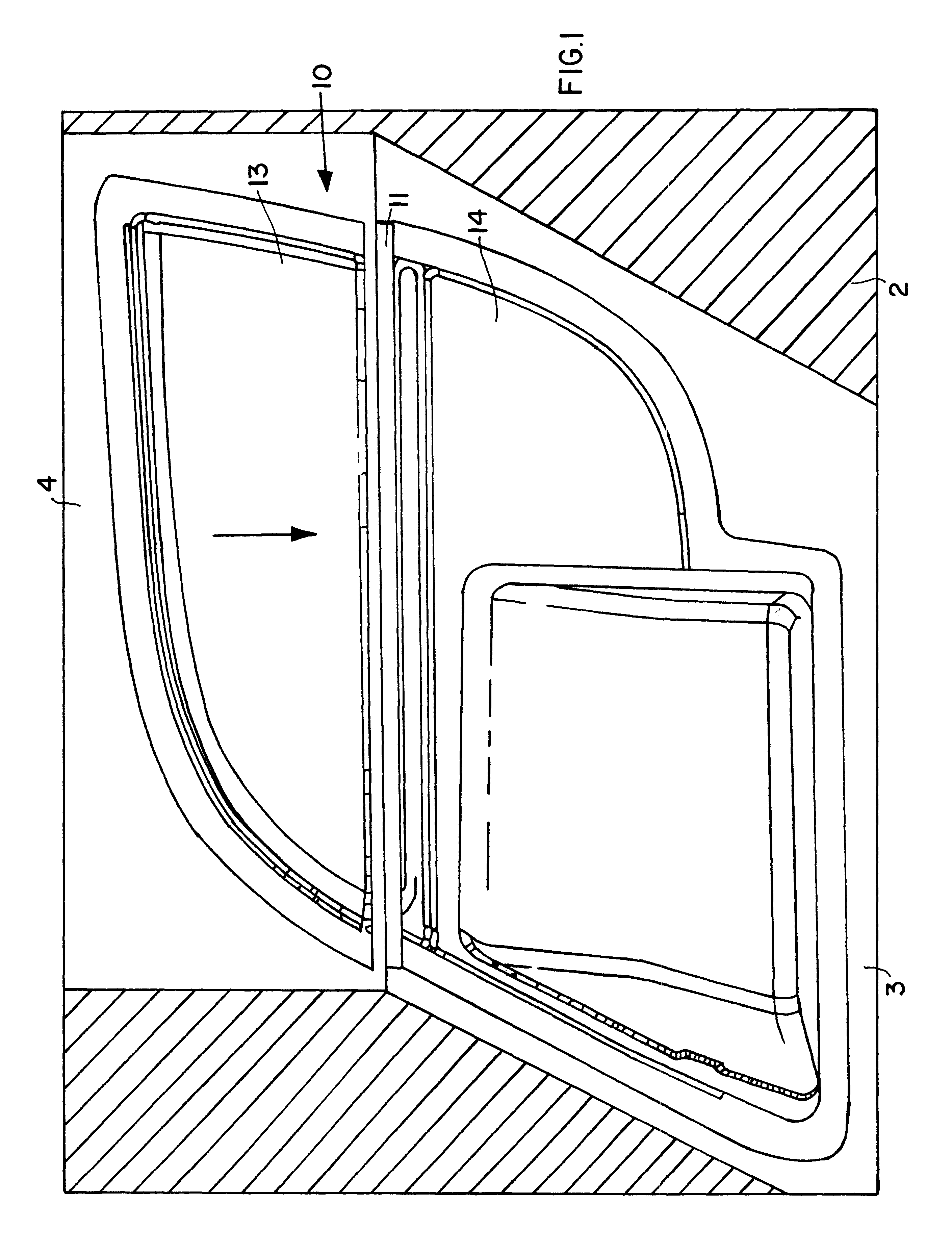
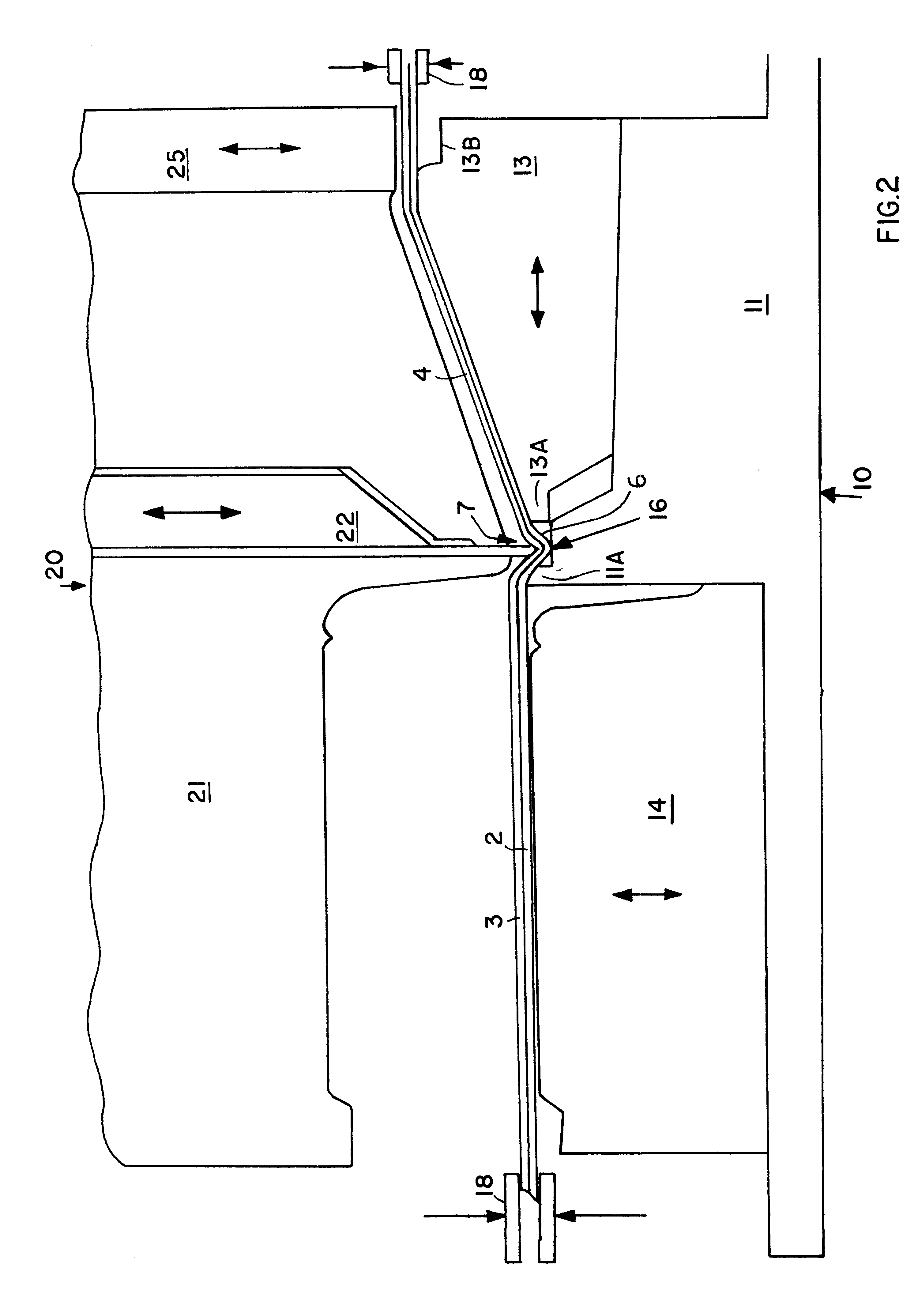
With reference to FIGS. 1 and 4, an example of a trim component 1 according to the invention is an interior door trim panel for an automobile, comprising a substrate 2 with two different cover sheets, namely a cover film 3 and a cover cloth 4, applied thereon. The two cover sheets, namely the film 3 and the cloth 4 are not pre-spliced together, but rather come together with their respective bordering ...


PUM

PropertyMeasurementUnit
angleaaaaaaaaaa
gap widthaaaaaaaaaa
angleaaaaaaaaaa

Abstract

A trim component (1) includes a substrate (2) and two different cover materials (3, 4), which are not spliced together but are independently adhesively bonded onto the substrate (2) by a hot-melt contact adhesion. The junction (7) is received in a valley (6) of the substrate that is pinched closed using a molding apparatus that includes a horizontally movable pinching stamp (13) which forms a pinching gap (16) relative to a protruding edge (11A) of a fixed mold tool (11). A tucking blade (22) cooperates with a counter-clamping blade (26) to clampingly hold and then press the substrate and junction of the cover sheets into the pinching gap. The tucking blade is then retracted while the pinching stamp pinches closed the pinching gap, to form a tightly closed valley in the substrate with the junction cleanly pinched therein.

Description

The invention relates to a method and an apparatus for making a trim component and especially an interior trim panel for a motor vehicle, wherein the decorative covering of the trim component includes two different cover materials.BACKGROUND INFORMATIONIn the automotive industry, it has become known to use interior trim components such as interior door panels, dashboards, and the like having a decorative covering including two different cover materials on the same trim component. Such a trim component having a two-part cover material is desired by consumers, for example to achieve a "two-tone effect" in which the two different cover materials have different colors, or a high value or "luxury effect" in which the two different cover materials are different types of materials such as a decorative cover film and a decorative cloth, or in which the different cover materials have different degrees of "soft touch" padding or the like.In order to make such vehicle trim components having tw...

Claims


Application Information

Patent Timeline
Patent Type & Authority Patents(United States)
IPC IPC(8): B29C51/14B29C53/00B29C51/08B29C53/36B60R13/02B29C51/26B29C51/30B29C65/00
CPCB29C51/14B29C53/36B29C66/13B60R13/02B29C51/087B29C65/00B29C51/082Y10T156/1043B29C51/262B29C51/30B29C2063/022B29K2023/00B29K2023/12B29K2311/10B29L2031/3014B60R2013/0281B60R2013/0293Y10T156/1044Y10T156/1031B29C66/45B29C66/1312B29C66/135B29C66/431B29C65/02
Inventor SPENGLER, GERHARD
Owner HERBERT OLBRICH
Why Eureka
Try Eureka