Dielectric filter, antenna duplexer, and communications appliance

a technology of dielectric filters and duplexers, applied in the direction of coupling devices, electrical devices, waveguides, etc., can solve the problems of filter characteristic distortion, inability to meet the needs of users,

Inactive Publication Date: 2003-03-04
PANASONIC CORP
View PDF4 Cites 14 Cited by
  • Summary
  • Abstract
  • Description
  • Claims
  • Application Information

AI Technical Summary

Problems solved by technology

However, to actually realize the configuration as shown in FIG. 32 as a dielectric filter, the long line of the transmission line electrode, which is a primary line of the filter, does not allow the transmission line having the length of 1 / 4 of the wavelength corresponding to the resonance frequency of the resonator to function as is on a dielectric layer which has a finite space.
The above mentioned configuration of a transmission line has the problem that it incurs the deterioration due to a loss in the pass band frequency of a dielectric filter forming the band rejection characteristic around the resonance frequency of the resonator.
Therefore, as shown in FIG. 36, there has been the problem that the rejection band is necessarily narrow. FIG. 35 is a Smith chart showing the state.
Therefore, when the above mentioned filter is used for a antenna duplexer, there has been the problem that a filter characteristic has distortion, etc.

Method used


Image

  • Dielectric filter, antenna duplexer, and communications appliance
  • Dielectric filter, antenna duplexer, and communications appliance
  • Dielectric filter, antenna duplexer, and communications appliance

Examples


first embodiment

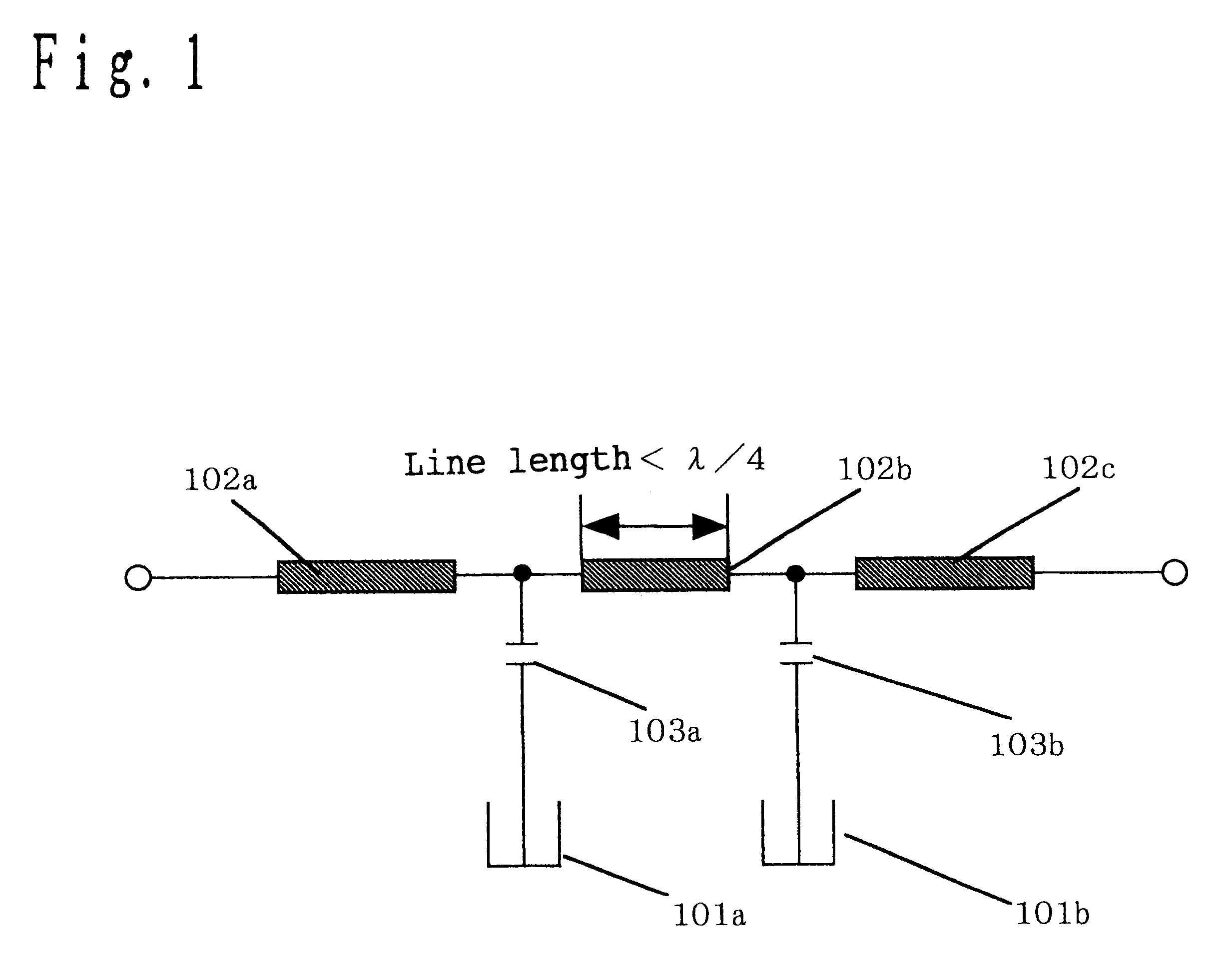
FIG. 1 shows an equivalent circuit of the filter according to a first embodiment of the present invention.

In FIG. 1, a filter forming a band rejection characteristic around the resonance frequency of a resonator is configured by a circuit in which a transmission line 102 having input / output terminals at both ends is connected to two resonators 101a and 101b respectively th rough capacitors 103a and 103b.

In FIG. 1, since the resonators 101a and 101b are connected parallel to the transmission line th rough the capacitors, the resonators 101a and 101b form an attenuation pole around the resonance frequency, and functions as a filter having a band rejection characteristic.

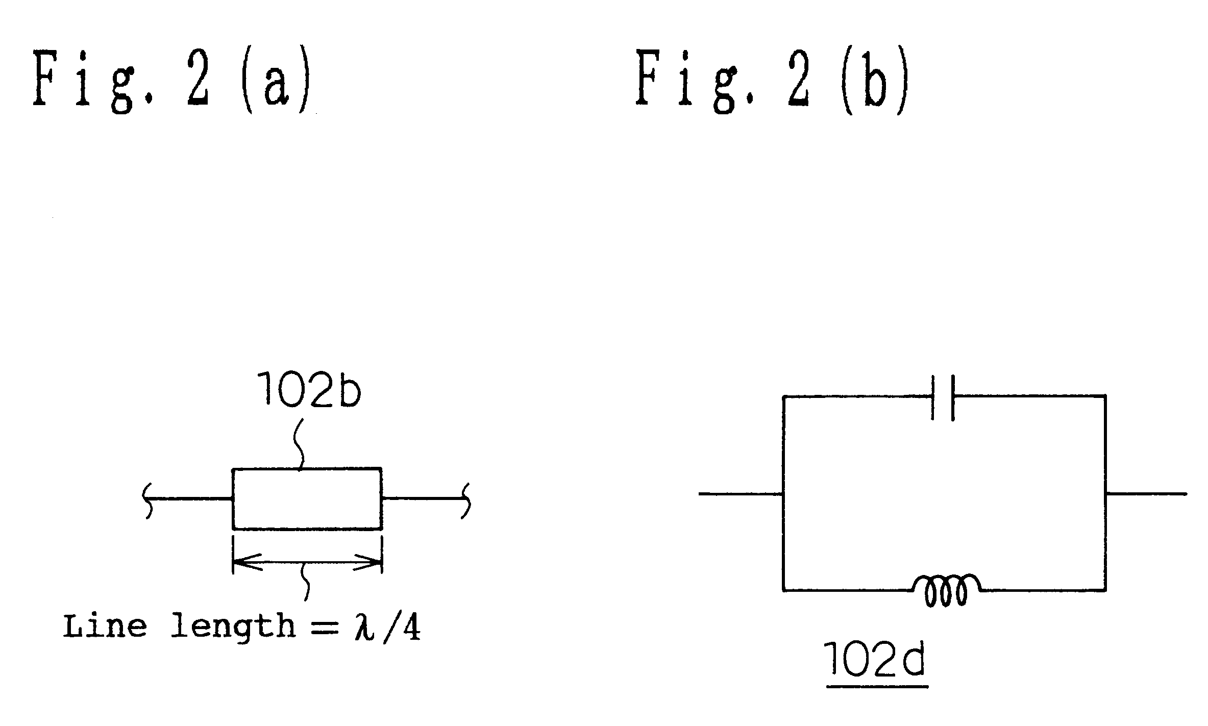
Conventionally, in the filter theory, it is necessary to have infinite impedance at the resonance frequency of a resonator to form a band rejection characteristic. To attain th is, as shown in FIG. 2(a) the line length of the transmission line 102b is set as 1 / 4 of the wavelength corresponding to the resonance frequenc...

second embodiment

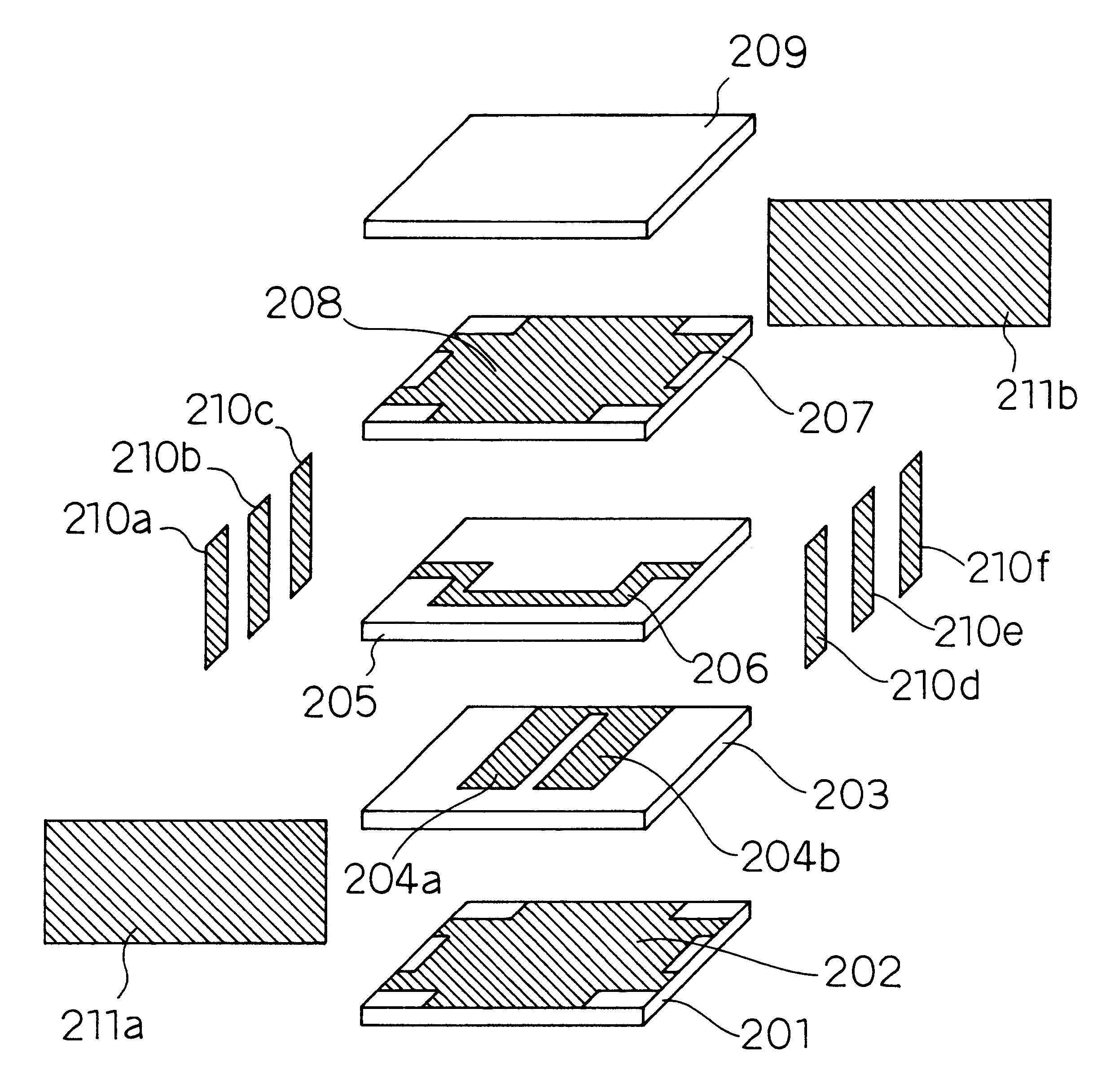
FIG. 4 is a analytic oblique view of the dielectric filter having a layered structure according to a second embodiment of the present invention. FIG. 5 is a projection view of a resonator electrode and a transmission line electrode forming th e dielectric filter in a layered structure. In FIG. 4, the dielectric filter according to the present embodiment has a first shield electrode 202 on the top surface of a first dielectric layer 201, a second dielectric layer 203 above the first shield electrode 202, resonator electrodes 204a and 204b on the top surface of the second dielectric layer 203, a third dielectric layer 205 above the resonator electrodes 204a and 204b, a transmission line electrode 206 between input / output terminals on the top surface of the third dielectric layer 205, a fourth dielectric layer 207 above the transmission line electrode 206, a second shield electrode 208 on the top surface of the fourth dielectric layer 207, and a fifth dielectric layer 209 above the sec...

third embodiment

FIG. 13 is an analytic oblique view of the structure of the dielectric filter according to a third embodiment of the present invention. Since the present embodiment is basically the same as the second embodiment in structure, corresponding units are assigned the same numbers, and the detailed explanation is omitted here. According to the present embodiment, second resonator electrodes 212a and 212b are provided on the top surface of the fifth dielectric layer 209, a third resonator electrode 213a is connected to the second resonator electrode 212a, and a third resonator electrode 213b is connected to the second resonator electrode 212b. With the configuration, the resonance frequency can be adjusted by trimming the second resonator electrodes 212a and 212b using a luter, etc.

With the above mentioned configuration, in addition to the effect as a dielectric filter similar to that according to the second embodiment, an adjustable frequency range can be extended by providing the second ...


PUM


Abstract

A dielectric filter including a plurality of resonators, and at least one transmission line provided among said plurality of resonators. A band rejection characteristic is formed around a resonance frequency of the resonator, and a line length of the transmission line is shorter than ¼ of a wavelength corresponding to the resonance frequency of the resonator.

Description

1. Field of the InventionThe present invention relates to a small dielectric filter used for a high frequency radio appliance such as a portable telephone, etc., a dielectric filter which has strip line type resonator electrodes on a dielectric substrate, and connects them in electromagnetic field, a antenna duplexer, etc.2. Related Art of the InventionRecently, dielectric filters have been widely used as high frequency filters of portable telephones, etc., and have been requested to be smaller and thinner. Under the situation, a laminated dielectric filter which can be thinner than a coaxial type filter is expected to have a higher market share.An example of the conventional laminated dielectric filter is described below by referring to the attached drawings.FIG. 32 is an analytic oblique view of the structure of a conventional dielectric filter.FIG. 33 shows an equivalent circuit of the dielectric filter shown in FIG. 32.In FIG. 32, the dielectric filter is a structure including: ...

Claims


Application Information

Patent Timeline
Patent Type & Authority Patents(United States)
IPC IPC(8): H01P1/203H01P1/213H01P1/20
CPCH01P1/2135H01P1/20345
Inventor MAEKAWA, TOMOYAKUSHITANI, HIROSHISHIGEMURA, HIROSHIYAMADA, TORUISHIZAKI, TOSHIONAKAKUBO, HIDEAKI
Owner PANASONIC CORP
Why Eureka
Try Eureka