
Rake receiver

a receiver and antenna technology, applied in the field of radio systems, can solve the problems of high-power interference sources, inability to separate multipath propagated signal components, and interference of each antenna

Inactive Publication Date: 2003-03-04
NOKIA TECH OY
View PDF11 Cites 81 Cited by
  • Summary
  • Abstract
  • Description
  • Claims
  • Application Information

AI Technical Summary

Problems solved by technology

On the radio path, the signal will include not only the desired signal but also noise and interference caused by other users or systems.
However, this method presupposes that the interference of each antenna is independent.
This presupposition is not always true in actual cellular radio networks, but it is conceivable that the same interference is present at each antenna.
However, the method has been used only in systems utilizing the Time Division Multiple Access (TDMA) method, these systems often being incapable of separating multipath propagated signal components.
In a spatially coloured interference field, a high-powered interference source can decrease the performance of the receiver because the Rake fingers are allocated to the wrong chip delays.

Method used


Image

  • Rake receiver
  • Rake receiver
  • Rake receiver

Examples


Embodiment Construction

In the following examples, embodiments of the invention are described in the Universal Mobile Telephone System (UMTS) without restricting the invention to it.

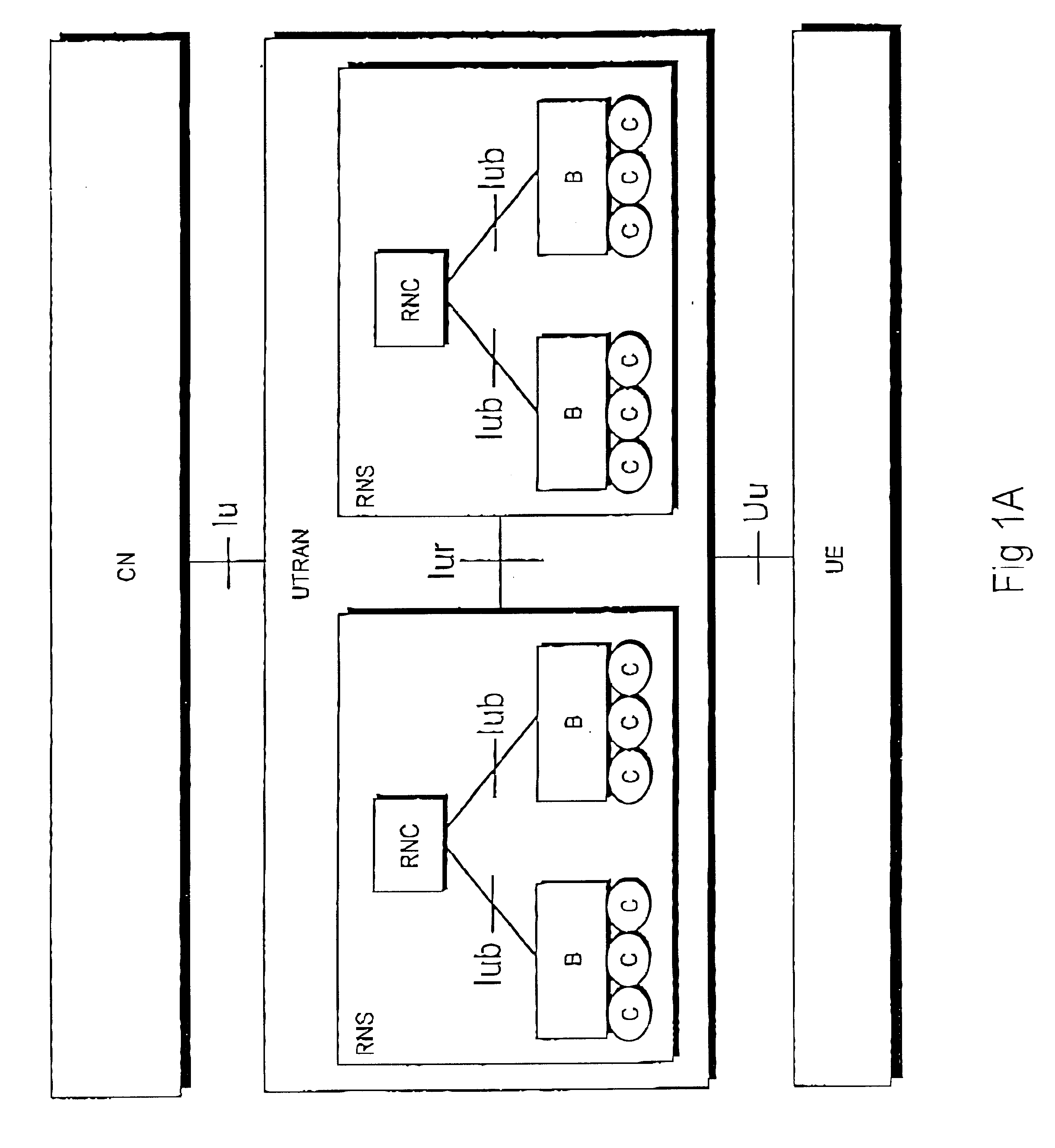
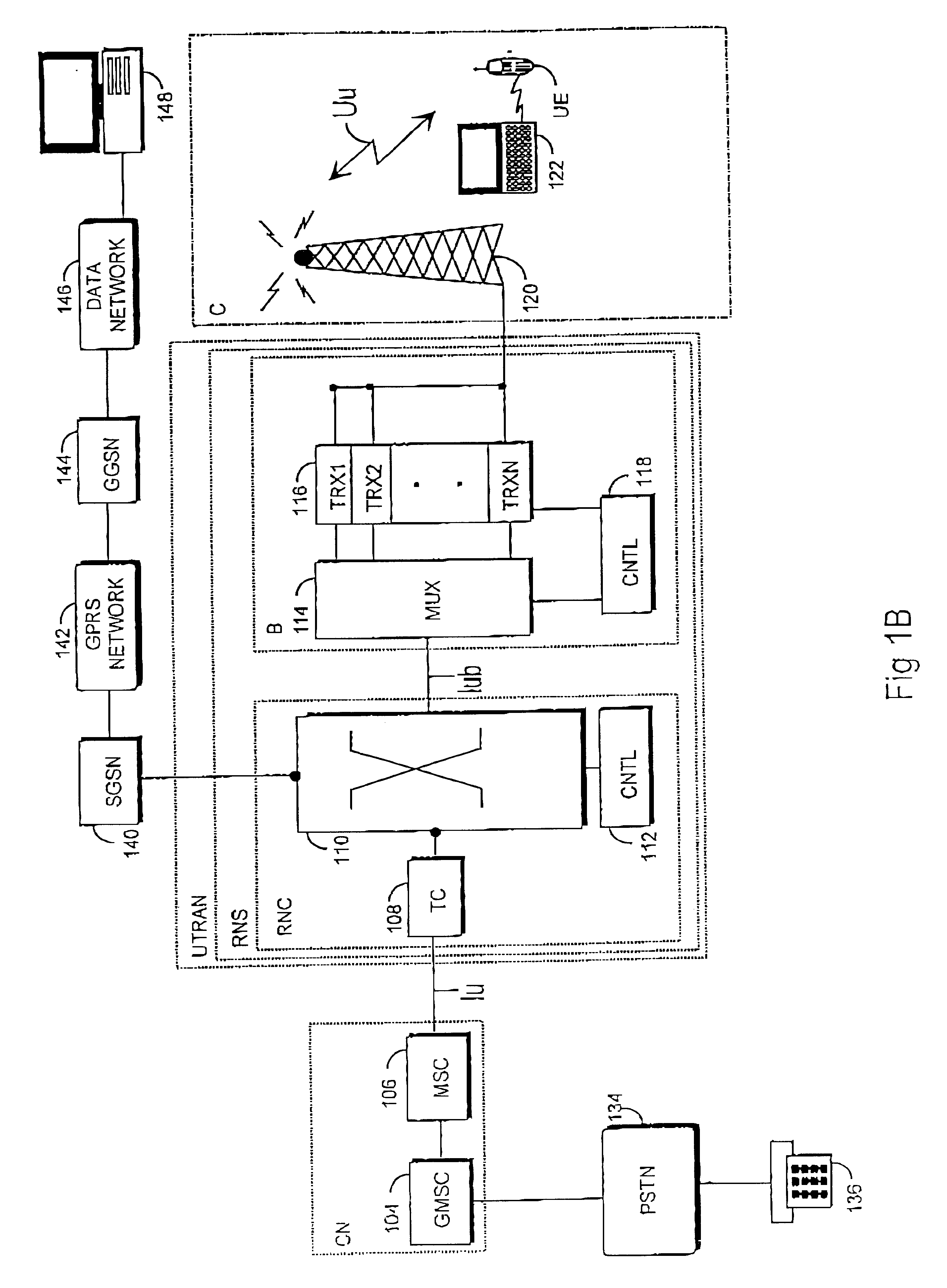
The structure of a universal mobile telephone system is explained referring to FIGS. 1A and 1B. FIG. 1B comprises only the blocks that are essential for the description of the invention, but it is obvious to one skilled in the art that a conventional mobile telephone system also comprises other functions and structures, which need not be explained here in more detail. The main parts of a mobile telephone system are a Core Network CN, a UMTS terrestrial radio access network UTRAN and User Equipment UE. The interface between the CN and the UTRAN is called Iu and the air interface between the UTRAN and the UE is called Uu.

The UTRAN comprises Radio Network Subsystems RNS. The interface between the RNSs is called lur. An RNS comprises a Radio Network Controller RNC and one or more nodes B. The interface between the RNC and B is call...


PUM


Abstract

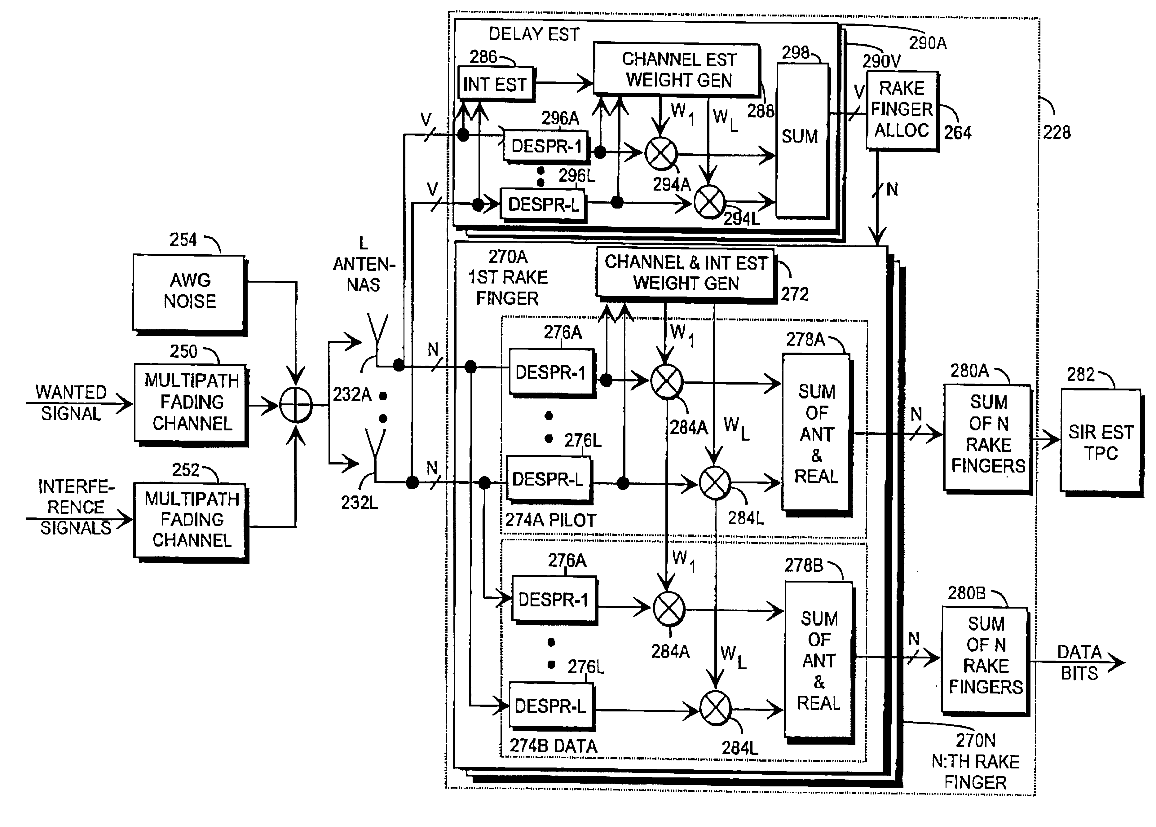
The invention relates to a Rake receiver of a CDMA system using IRC. The Rake receiver comprises at least two antenna branches, at least one Rake finger, and a delay estimator. The delay estimator comprises a despreader and an allocator for selecting at least one delay, and allocating a Rake finger for processing the signal component found by informing the Rake finger of the delay found. The delay estimator further comprises: a channel estimator, an interference estimator for generating an interference signal, a weighting coefficient part for providing each antenna branch with weighting coefficients maximizing the Signal-to-Interference-and-Noise Ratio, a multiplier for multiplying the pilot part by a weighting coefficient, and an antenna branch summer for combining the despread pilot parts, received via the separate antenna branches and multiplied by the weighting coefficient, to one combined pilot signal, on which combined pilot signal the selection is based in the allocator.

Description

The invention relates to a Rake receiver of a radio system using a Code Division Multiple Access (CDMA) method.DESCRIPTION OF THE BACKGROUND ARTIn radio systems, diversity methods of different kinds are used for increasing the coverage area and / or capacity of the system. As to this publication, space diversity, i.e. antenna diversity, polarization diversity and multipath diversity are of interest. Space diversity indicates that antennas are positioned sufficiently far from each other to achieve a sufficient decorrelation between signals received via the separate antennas. An interesting kind of polarization diversity is implicit polarization, i.e. a signal is sent on one polarization level, but received by cross-polarized antennas. Multipath diversity refers to diversity created by multipath propagated signal components, this diversity being usable in a system, such as a CDMA system, in which the bandwidth of a signal is much wider than the coherent bandwidth of a channel.In a CDMA ...

Claims


Application Information

Patent Timeline
Patent Type & Authority Patents(United States)
IPC IPC(8): H04B7/08H04B1/707
CPCH04B1/7115H04B7/0857H04B7/0897H04B1/7117H04B1/712H04B2201/709727H04B2201/70701H04B7/0851
Inventor TIIROLA, ESAYLITALO, JUHA
Owner NOKIA TECH OY
Learn More