

Inflatable electrode for temporary pacing
a technology of inflatable electrodes and electrodes, which is applied in the field of balloon electrodes, can solve problems such as unsuitable sensing activities
- Summary
- Abstract
- Description
- Claims
- Application Information
AI Technical Summary
Problems solved by technology
Method used
Image

Examples
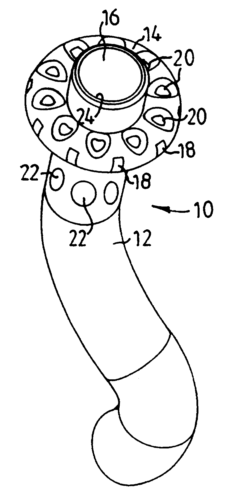
first embodiment
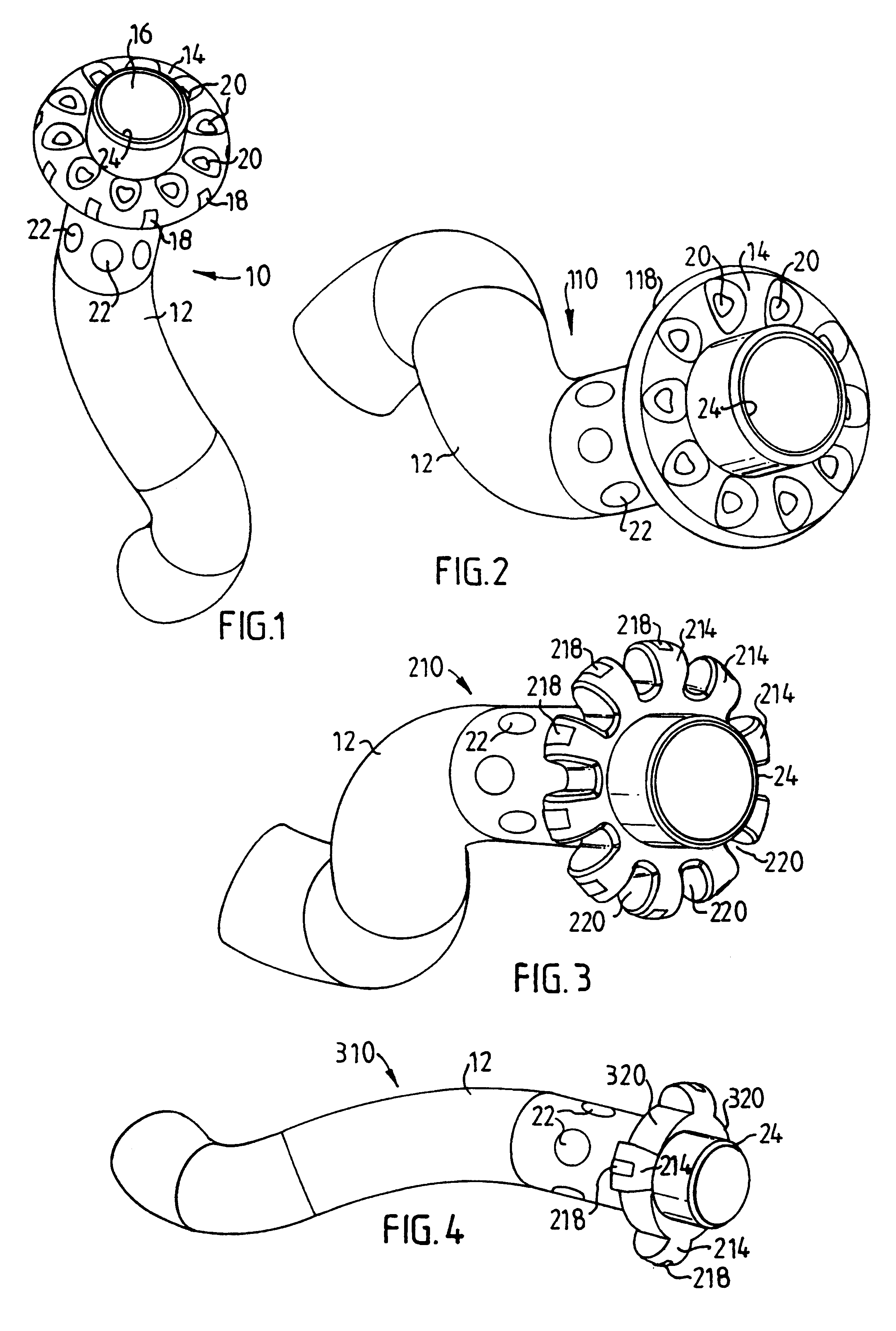
A second embodiment of a temporary balloon electrode 110 of the present invention shown in FIG. 2 differs from the first embodiment in FIG. 1 only in that the plurality of electrode surface contact members 18 have been replaced by a single ring-shaped contact member 118, which is made collapsible to facilitate insertion of the balloon electrode 110 in the deflated condition thereof. To this end the ring-shaped contact member 118 may consist of an expandable annular coil spring element or the like.
third embodiment
a temporary balloon electrode 210 according to the present invention is illustrated in FIG. 3. In this embodiment the balloon member has a plurality of radially expandable hollow sections 214, which define blood flow passages 220 between the adjacent sections 214. Supplemental blood flow bypass holes 22 may also be arranged in the catheter downstream of the balloon member 210. Individual electrode surface contact members 218 are located at the tip of the radially expandable sections 214 and may--like in the first embodiment--be connected in parallel or individually to an external PSA through leads (not shown).
fourth embodiment
FIG. 4 illustrates a balloon-type electrode 310, which differs from the third one in FIG. 3 only in that there are only four radially expandable hollow sections 214. This results in wider blood flow passages 320 between adjacent expanded sections 214.
In all four embodiments of the balloon electrode of the present invention the balloon member may consist of latex and have a diameter in the approximate range of 2.5-20 mm in the inflated condition and an axial length of approximately 2.5 mm. X-ray markers, e.g. a layer of lead or tantalum, may be provided on the catheter 12, e.g. on each side of the balloon member 14;214 to indicate a proper electrode position for a later inserted, permanent electrode stent for pacing or other stimulation or sensing purposes. Alternatively, the guide wire used for the positioning of the balloon electrode may be provided with X-ray markers to indicate the selected position for the electrode stent. The distal end of the catheter 12 defining the opening 2...
PUM
 Abstract
Description
Claims
Application Information