Eye dropper positioning device

a positioning device and dropper technology, applied in the field of eye dropper positioning device, can solve the problems of device interference with easy removal of bottle cap, design interference with easy access to bottle cap, and do not address the problem of removal and replacement of the cap of the ophthalmic solution containing bottl

Inactive Publication Date: 2003-03-11
SHERMAN THOMAS M +1
View PDF12 Cites 17 Cited by
  • Summary
  • Abstract
  • Description
  • Claims
  • Application Information

AI Technical Summary

Problems solved by technology

The eye engaging portion of this device interferes with easy removal of the bottle cap.
Furthermore, their very design interferes with easy access to the bottle cap.
While these patents accomplish many fine results, they do not address the problem of removal and replacement of the cap of the ophthalmic solution containing bottle.
The close location of these features makes it difficult to remove the bottle cap before use and replace the cap after use.
This impediment to removal and replacement of the bottle cap frustrates the user and encourages the user to leave the cap off, thus creating a potentially unsanitary condition within the bottle containing ophthalmic solution.

Method used


Image

  • Eye dropper positioning device
  • Eye dropper positioning device
  • Eye dropper positioning device

Examples


embodiment 1

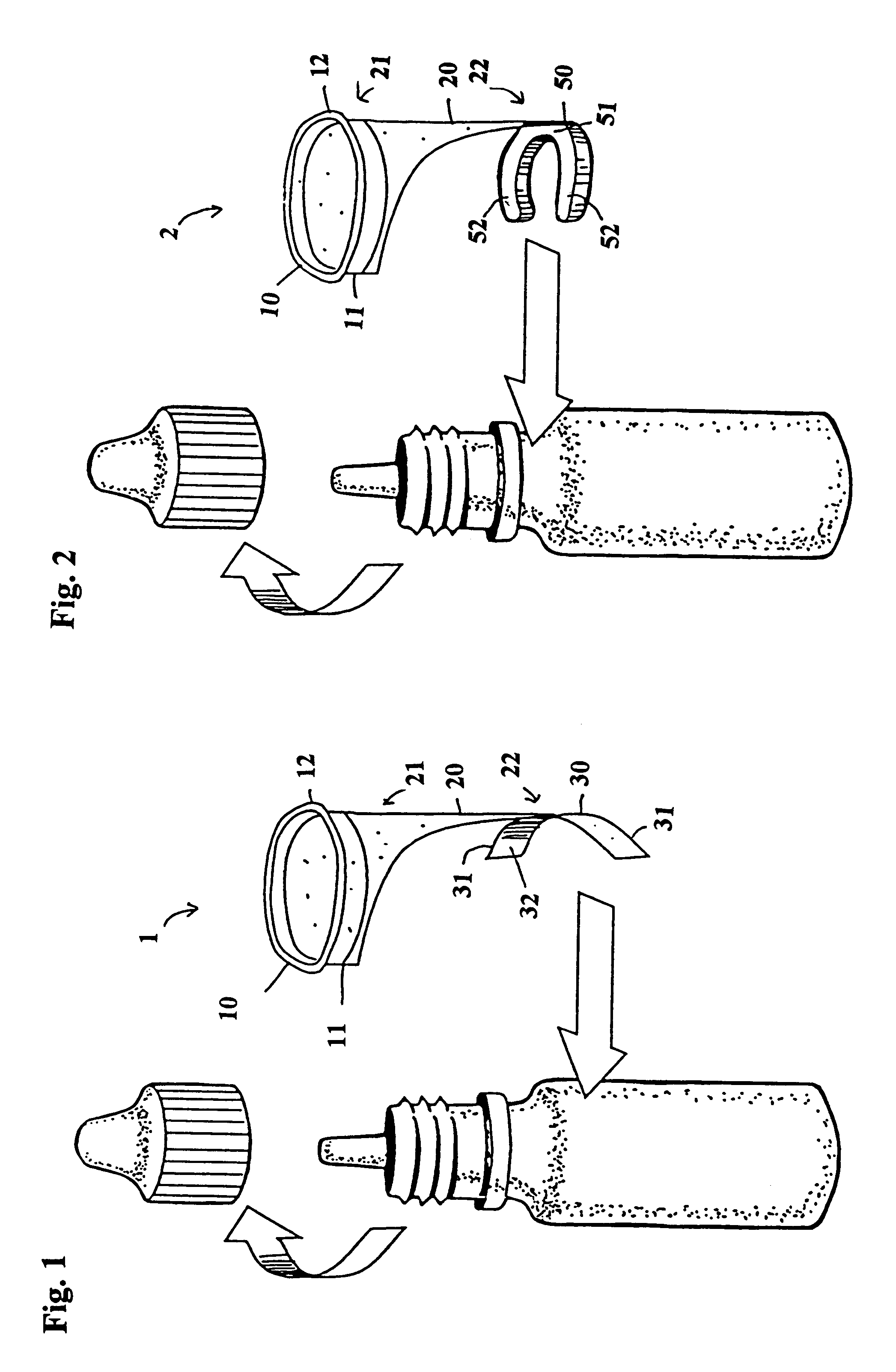
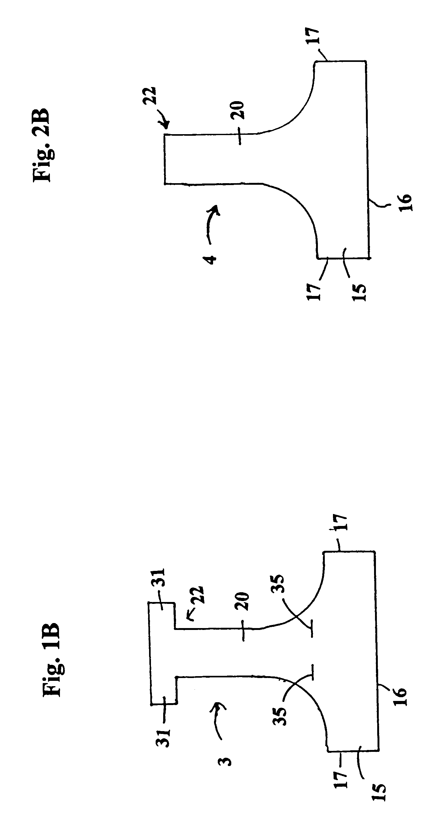
One method of constructing the first preferred embodiment 1 is to take a piece of thin flexible plastic material and cut a shape 3 as illustrated in FIG. 1B. On the shape is a substantially rectangular base portion 15. One long side of the base portion 15 gradually extends outward to form the extension piece 20. When looking at the base portion 15 and extension piece 20, they appear to form a T-shape wherein the junction of the T is a smooth and continuous curve, as opposed to discontinuous. The extension piece 20 has at the second end 22, two small rectangular arms 31 projecting transverse to the long direction of the extension piece 20. The eyelid engaging ring 10 is formed by rolling a lower end 16 of the base 15, preferably with the roll directed to an outside surface of the plastic material. The roll does not consume the entire width of the base portion 15, since eyelid engaging ring 10. Opposite outside ends 17 of the base 15 are then attached to each other to form the ring 10...

embodiment 2

One method of constructing the second preferred embodiment 2 is to take a piece of thin flexible plastic material and cut a T-shape 4 as illustrated in FIG. 2B. The T-shape comprises a substantially rectangular base portion 15. One long side of the base portion 15 gradually extends outward to form the extension piece 20. When looking at the base portion 15 and extension piece 20, the junction of the T form a smooth and continuous curve, as opposed to discontinuous. The eyelid engaging ring 10 is formed by rolling a lower end 16 of the base 15, preferably with the roll directed to an outside surface of the plastic material. The roll does not consume the entire width of the base portion 15, since the unused portion forms the support flange 11 which runs along the periphery of the eyelid engaging ring 10. Opposite outside ends 17 of the base 15 are then attached to each other to form the ring 10 itself. Alternately, device 2 may be manufactured by injection molding techniques or other ...


PUM


Abstract

The present invention is directed to a device to aid in the placement of eye drops from an ophthalmic medication containing bottle. The device of the present invention is designed to be attached to the bottle at all times, including while in use. Furthermore, the present invention is specifically designed to aid in the easy removal and replacement of ophthalmic solution containing bottle caps. The present invention, in its most basic form, comprises an eye ring, a bottle attaching portion and a flexible extension connecting the eye ring to the bottle attaching portion, wherein the eye ring and flexible extension may be moved off of the bottle axis to permit easy removal and replacement of the bottle cap.

Description

The present invention relates to the ophthalmic solution dispensing devices, and has particular reference to a novel construction for an eye dropper positioning guide which works in combination with an ophthalmic medicant bottle, which includes a dispensing nozzle.A common malady which affects eyes is that they become irritated due to dust and small foreign objects which are common pollutants in the air. One method for alleviating this irritation is the application of an eyewash, a liquid medicant, to the eyes. Most eyewashes are contained in a bottle which incorporates a dropper mechanism in the top. However, these eye droppers are difficult to operate. Most people have difficulty in applying drops due to the extreme sensitivity of their eyes. Moreover, poor vision makes it difficult to properly position or align an eye dropper bottle relative to the eye frequently causes drops to be improperly applied. Thus, the user quite often wastes eyewash by missing the intended eyeball.Thus ...

Claims


Application Information

Patent Timeline
Patent Type & Authority Patents(United States)
IPC IPC(8): A61F9/00
CPCA61F9/0026
Inventor SHERMAN, THOMAS M.GLASS, THEODORE A.
Owner SHERMAN THOMAS M
Why Eureka
Try Eureka