Excavation bit for a drilling apparatus
a drilling apparatus and excavating bit technology, applied in the field of excavating bit, can solve the problems of more cutters, limited bore size of operators, and greater torque and thrust to be applied to the bit,
- Summary
- Abstract
- Description
- Claims
- Application Information
AI Technical Summary
Benefits of technology
Problems solved by technology
Method used
Image
Examples
embodiment 32
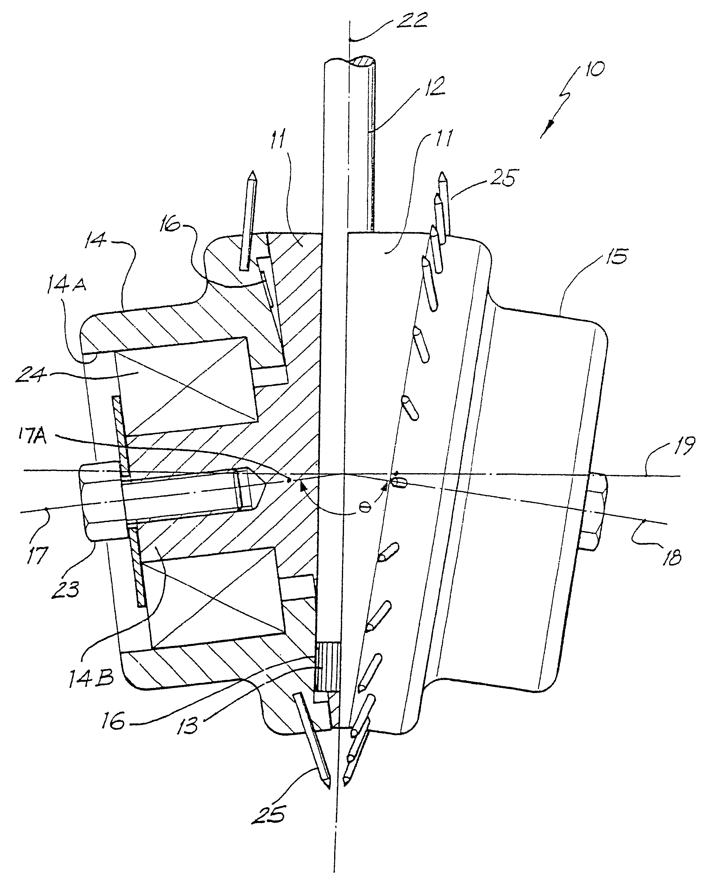
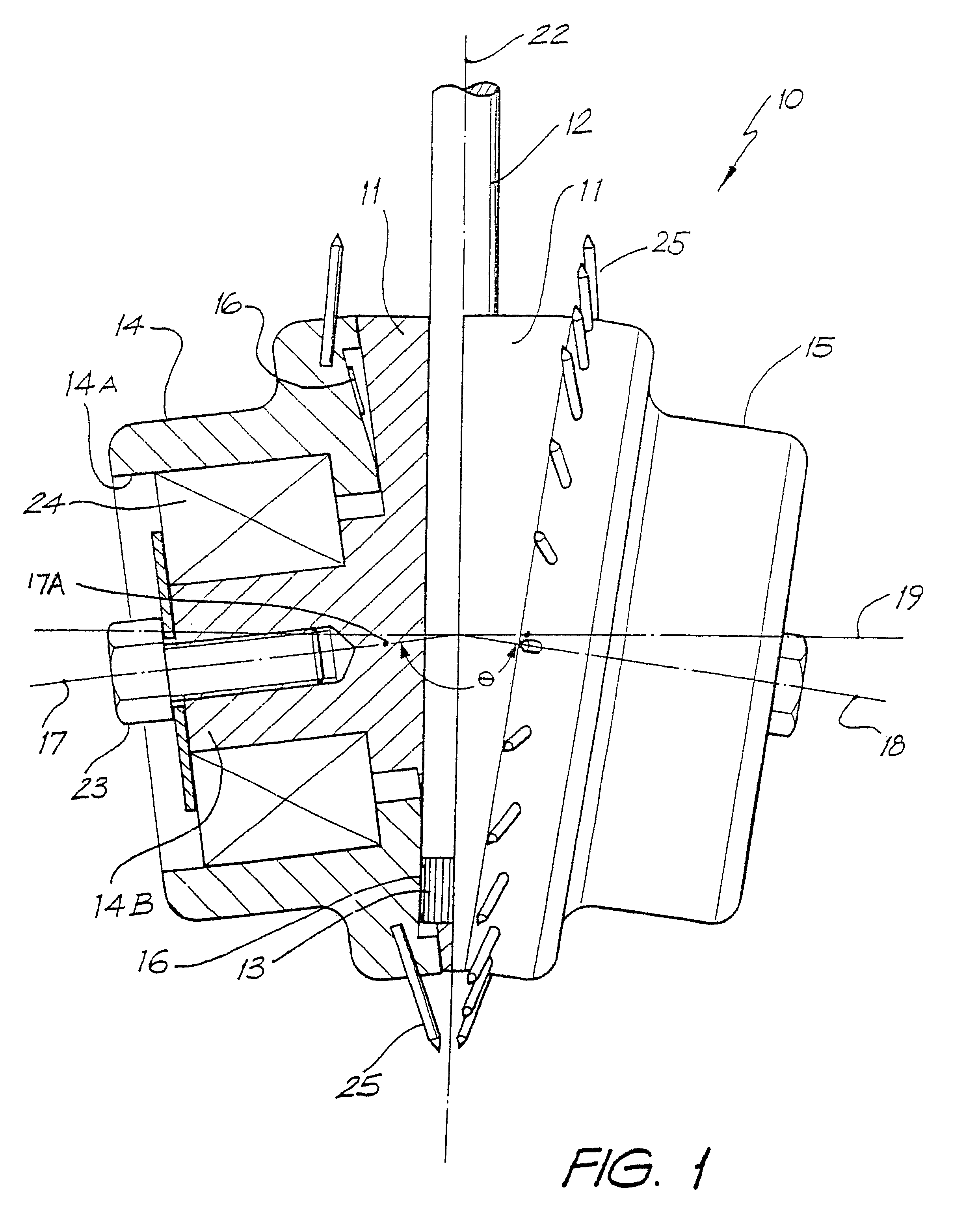
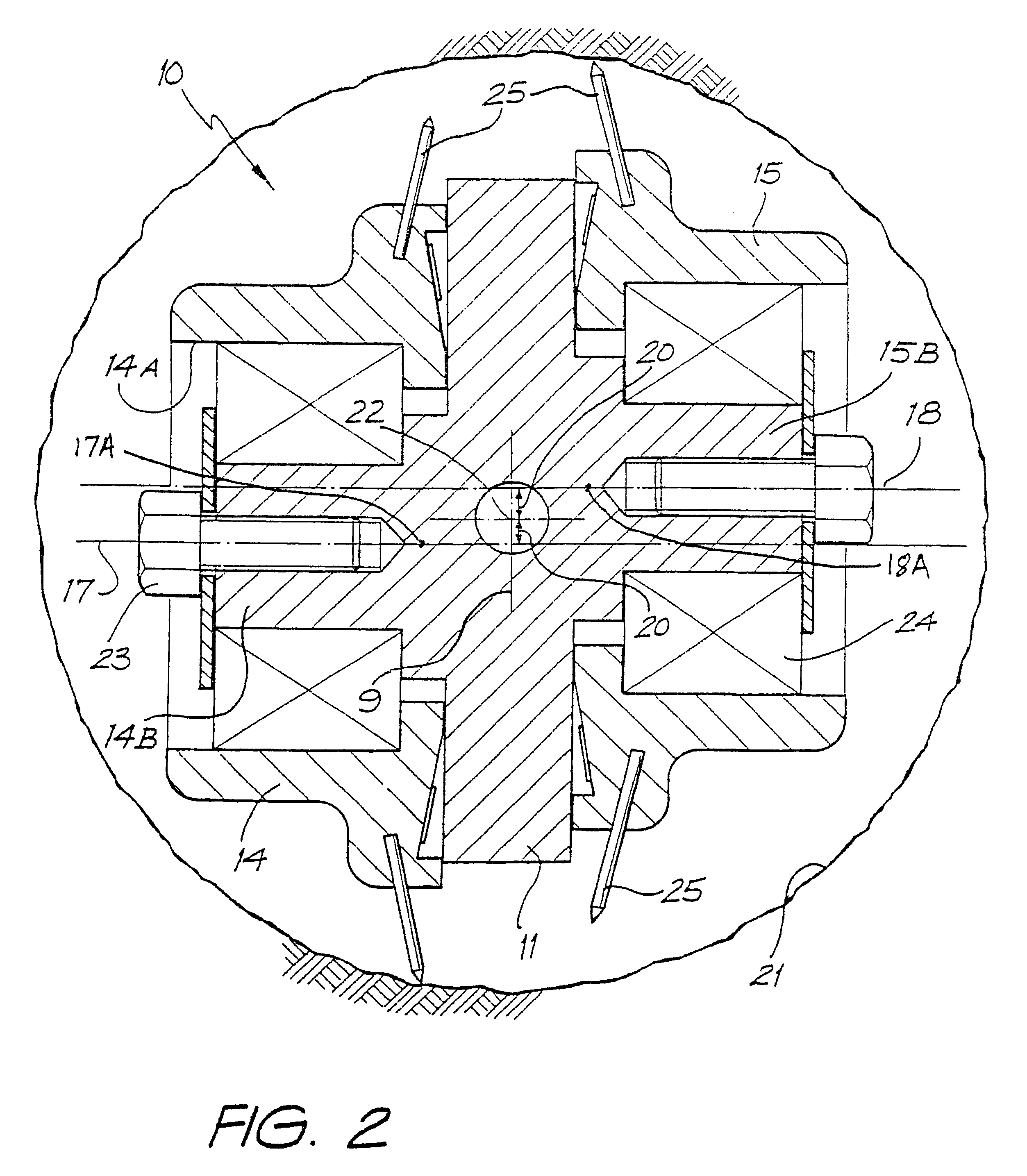
FIG. 5 illustrates a reaming embodiment 32 similar to that of FIG. 1, showing the surface to be reamed 21 after the pilot hole 29 is drilled. Pilot hole 29 also acts as a guide for the bit 32, as drill rods and drive shaft 12 are pulled through the pilot hole 29. The axes 47 and 48 of the carriers 14 and 15 are inclined above the first transverse axis 49. This allows the tips of the cutters 25 to angle toward each other and to engage as close to the pilot hole 29, without contacting the drill rod or drive shaft 12. By rotating drive shaft 12, without any externally imposed upward thrust (in direction of arrow 4), the bit 32 will thrust in the direction of arrow 4 due to the contact of the cutters 25 with the rock surface 21, and the contra-rotation of the carriers 14 and 15.
second embodiment
In FIG. 6 of the accompanying drawings there is diagrammatically depicted a In this embodiment the bore engaging end of the drive shaft 12 is provided with a pilot hole bit 74. Other detail of the apparatus is substantially the same in construction and operation as that described above with reference to FIG. 1.
As depicted in FIG. 6, the apparatus includes a pair of upper bearings 63 located about the drive shaft 12 and held in position thereon by means of a bearing retaining nut 64. Bearings 63 engage with the internal annular surface of a bearing carrier 62 which is bolted or otherwise secured to the main body 11. A seal carrier 60 is bolted or otherwise secured to the bearing carrier 62 and includes an annular seal 61. Similarly, the other (internal) end of the bearing carrier 62 includes an annular seal 61 which bears against the surface of the drive shaft 12. The main body 11 includes a further annular seal 69 about its periphery near the bore engaging end. Seal 69 bears agains...
fourth embodiment
FIG. 10 illustrates a fourth embodiment wherein the angle .theta. is approximately 120.degree.. In this embodiment, there are provided additional cutting teeth 25, which are mounted on side surfaces of the carrier 14, or if desired, they could also be mounted onto cover plate 73. These additional cutters assist in providing additional stability to the excavation bit, as it is excavating.
The angle .theta. affects the relationship between the torque in drive shaft 12 and the pushing effect of the cutting teeth 25 against the rock. If the angle .theta. high, but less than 180.degree. then the main body 11 will rotate by virtue of the reaction forces resulting from cutter engagement, to produce a moment about the longitudinal axis 22. As the angle .theta. decreases in size, the pushing effect increases and rotation speed increases. Simultaneously, as the angle .theta. decreases, so does the magnitude of thrust (in direction of arrows 4 (FIG. 3) or arrow X (FIG. 9), produced by the contr...
PUM
 Abstract
Description
Claims
Application Information
 - R&D
- Intellectual Property
- Life Sciences
- Materials
- Tech Scout
- Unparalleled Data Quality
- Higher Quality Content
- 60% Fewer Hallucinations
Browse by: Latest US Patents, China's latest patents, Technical Efficacy Thesaurus, Application Domain, Technology Topic, Popular Technical Reports.
© 2025 PatSnap. All rights reserved.Legal|Privacy policy|Modern Slavery Act Transparency Statement|Sitemap|About US| Contact US: help@patsnap.com


