Motor apparatus

a brushless motor and motor technology, applied in the direction of motor/generator/converter stopper, electronic commutator, dynamo-electric converter control, etc., can solve the problems of increased output voltage modification and adjustment, disordered position detection, and non-synchronous operation

Inactive Publication Date: 2003-03-25
III HLDG 12 LLC
View PDF10 Cites 49 Cited by
  • Summary
  • Abstract
  • Description
  • Claims
  • Application Information

AI Technical Summary

Problems solved by technology

Such prior art required, disadvantageously, to dispose a switching device, and a composition to control its driving.
On the other hand, the second prior art has an advantage of being able to transit to the synchronous operation by stationary position detection in a period of time shorter than the first prior; however, when the load driven by the rotor 13R varies, the position detection will be disordered by such variation, and disadvantageously, it can not transit to the synchronous operation by stationary position detection.
Such output voltage modification and adjustment increases, disadvantageously, the vibration and noise of the motor itself or compressor.
In such a prior art, as it is necessary to provide, besides overcurrent detection circuit, an overcurrent anomaly hold circuit, and an overcurrent anomaly cancel circuit, apparatus whose composition becomes complicated can not be supplied easily and at a low price, and in addition, anomaly or faults also happen in these overcurrent anomaly hold circuit or overcurrent anomaly cancel circuit, making the maintenance more difficult disadvantageously.

Method used


Image

  • Motor apparatus
  • Motor apparatus
  • Motor apparatus

Examples


first embodiment

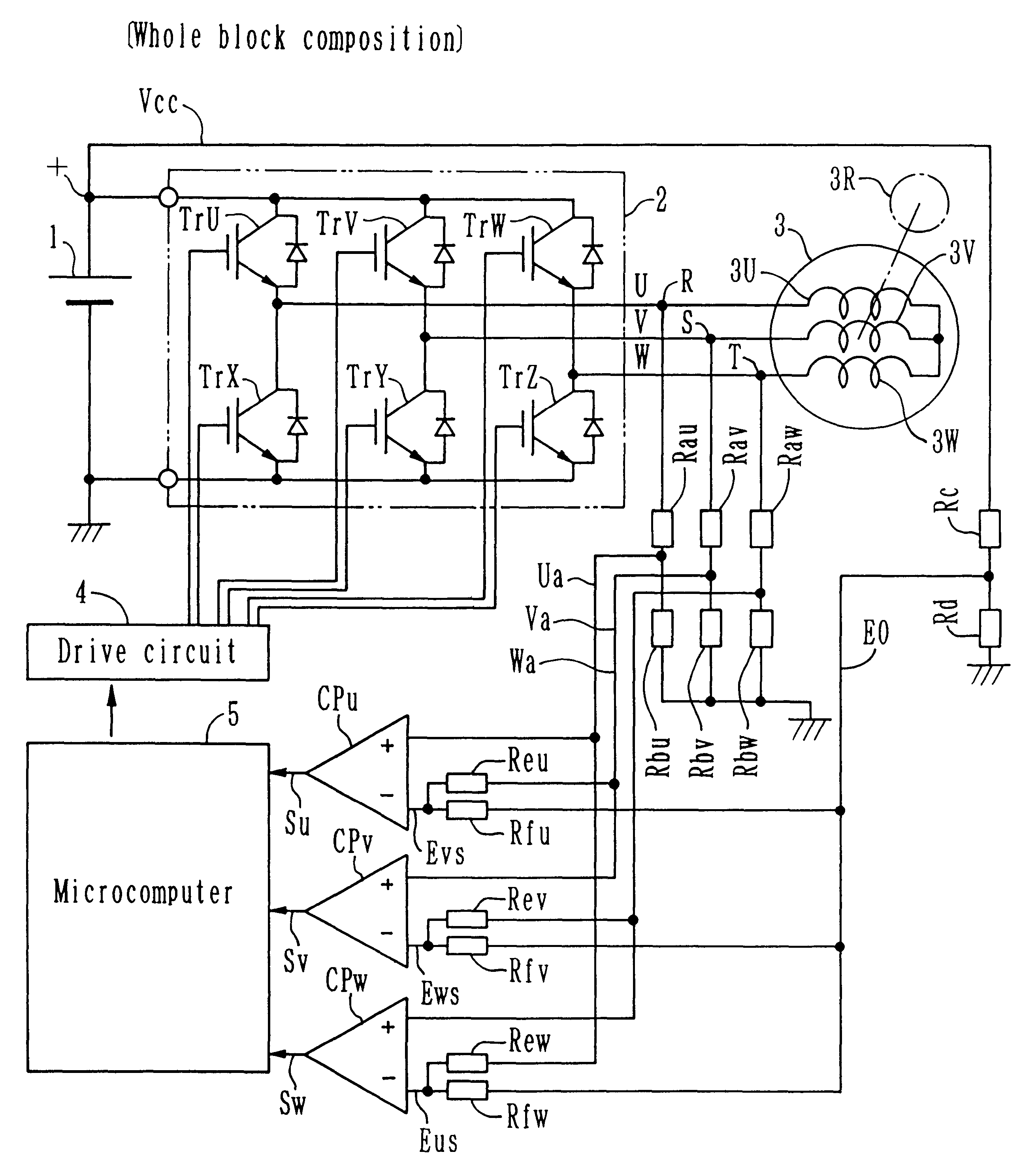
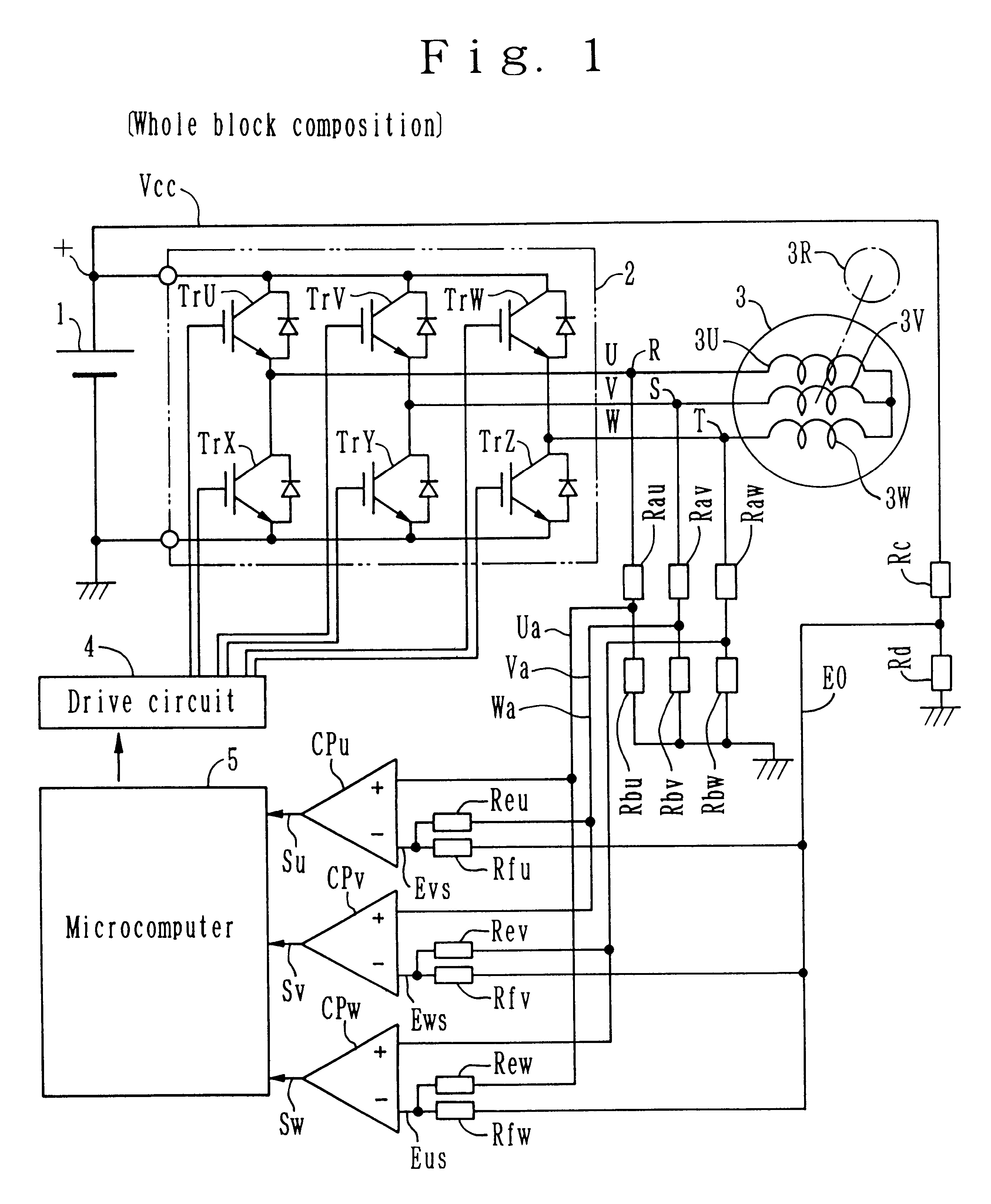
Now a first example shall be described referring to FIG. 1.about.FIG. 3. This first embodiment, on the whole, composes said first composition and second composition.

In FIG. 1, voltage input to respective positive terminal, namely, + terminal of respective comparator CPu, CPv, CPw is similar to said prior art.

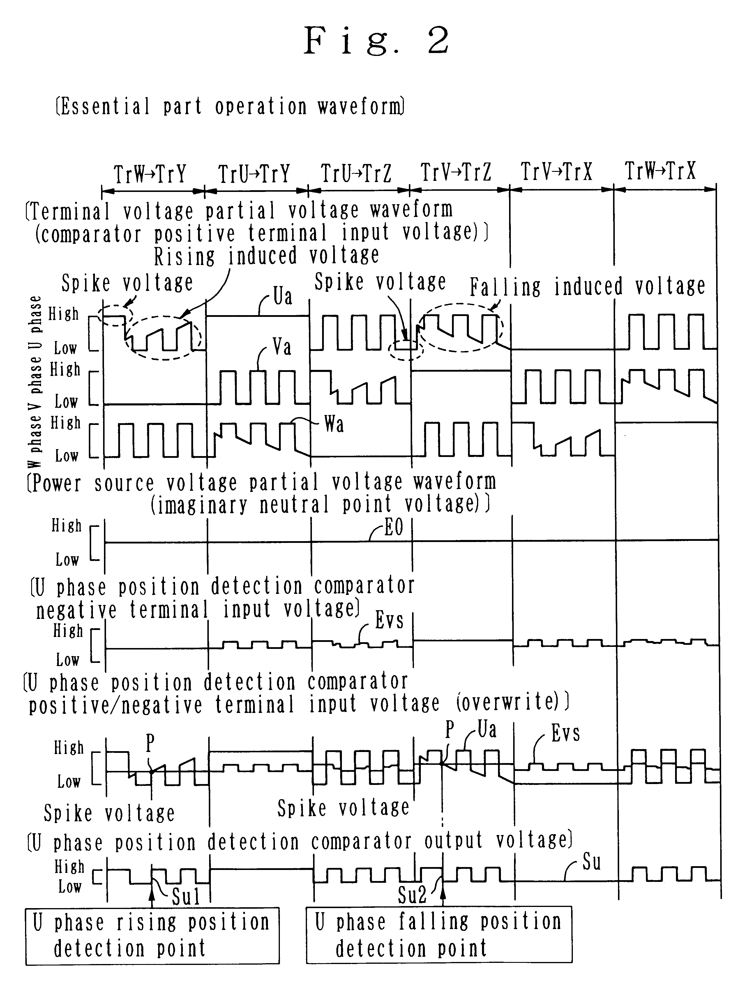
The bus voltage Vcc is divided by the bleeder circuit by the resistor Rd, Rc, becomes an imaginary neutral point voltage EO as [Power source voltage partial voltage waveform (imaginary neutral point voltage)] in FIG. 2, and is input to the resistor Rfu side of the bleeder circuit by the resistor Reu, Rfu, the resistor Rfv side of the bleeder circuit by the resistor Rev, Rfv, and the resistor Rfw side of the bleeder circuit by the resistor Rew, Rfw.

Voltage between U phase divided voltage Ua and the imaginary neutral point voltage E0 is divided at the bleeder circuit by the resistor Rew, Rfw, becomes a waveform whose amplitude of U phase divided voltage Ua is reduced as U phase vo...

second example

Now a second example shall be described referring to FIG. 4, FIG. 5. The composition of this second example composes said first composition and third composition. The composition of this second example is different from the composition of the first example of FIG. 1 in that, the voltage supplied to the resistor Reu is changed to the W phase divided voltage Wa, the voltage supplied to the resistor Rev is changed to the U phase divided voltage Ua, and the voltage supplied to the resistor Rew is changed to the V phase divided voltage Va.

Consequently, respective comparison voltage Eus, Evs, Ews input to the negative terminal side of respective comparator CPu, CPv, CPw are all changed to the comparison voltage obtained based on the phase preceding in the order, in respect of in respect of the phase of respective U phase divided voltage Ua, V phase divided voltage Va, W phase divided voltage Wa input to the positive terminal.

Therefore, concerning the comparison detection state in respecti...

third example

Now a third example shall be described referring to FIG. 1, FIG. 4, FIG. 6. The composition of this third embodiment is different from the composition of said first example and second example in that a condenser is provided for absorbing noise component of the voltage input to respective comparator CPu, CPv, CPw, and attenuating the waveform.

In the composition of FIG. 4, the input voltage to the positive terminal and the input voltage to the negative terminal of respective comparator CPu, CPv, CPw may overlap during the switching of respective transistor TrU.about.TrZ, and the output voltage of respective comparator CPu, CPv, CPw may possibly become unstable and provoke malfunction; therefore, an accurate position detection signal Su, Sv, Sw can be obtained by disposing, at least, at the point of input voltage of the positive terminal of respective comparator CPu, CPv, CPw, and absorbing noise and attenuating the waveform of the switching point of the pulse voltage. Also, in the com...


PUM


Abstract

A motor apparatus, such as a DC brushless motor, is provided for the obtaining a position detection signal by detecting the intersection of the divided voltage of a bus voltage and three phases of the divided voltage of the three phases by a comparator which results in the central position of a flat portion. For the divided voltage for the three phases of the respective positive terminal of the comparator, the comparison voltage obtained by dividing the voltage between the divided voltage for the three phases of the following phase in the order and the divided voltage of the bus voltage is applied to the respective negative terminal. As the comparison voltage is phase shifted, the position can be detected by making a slant position ahead of the flat point of the intersection. When the comparison voltage obtained by dividing the voltage between the divided voltage for the three phases of the preceding phase in the order and the divided voltage of the bus voltage is applied to the respective negative terminal, as the phase is shifted in the opposite direction, the position can be detected by making a slant position near the flat point of the intersection. Thereby, the motor apparatus having an intersection whose position is to be detected, can be detected precisely even when the intersection is a flat crossing and is unclear.

Description

1. Field of the InventionThis invention concerns a DC brushless motor apparatus allowing to control the inverter circuit driving by position detection signal obtained through the position detection of a motor apparatus, particularly.2. Background of the InventionAs for the composition of such DC brushless motor apparatus, for example, compositions as shown in FIG. 9, 21, 30 are disclosed by Japan Patent Application Laid-Open Hei 8-182378. In FIG. 9, 21, 30, the power source section 1, 11, 21 is a DC power source, and obtains an bus voltage Vcc of the inverter circuit 2, 12, 22 for obtaining a pulse modified voltage mentioned below, and obtains a DC power source, for example, by rectification and flattening of the AC power source.In FIG. 9, the inverter circuit 2, generates multi-phase, for instance, three-phase pulse width modified voltage of U-phase, V-phase and W phase, by controlling transistors TrU.about.TrZ, for instance, power transistor, IGBT device or the like, by means of d...

Claims


Application Information

Patent Timeline
Patent Type & Authority Patents(United States)
IPC IPC(8): H02P6/00H02M7/5387H02P6/14H02P6/18H02P6/20
CPCH02M7/53871H02P6/205H02P6/182H02P6/21
Inventor KATO, HIDEAKIOGAWA, TAKASHINOMOTO, TETSUOIZAWA, YUUICHI
Owner III HLDG 12 LLC
Why Eureka
Try Eureka