
Modem shelf

a modem and shelf technology, applied in the field of shelf in a relay rack, can solve the problems of low data transfer rate of current commercially available modem technology using pots, noise affecting adsl, and low data transfer rate of downstream data transfer possible with adsl, so as to preserve the integrity of high-speed data streams

Inactive Publication Date: 2003-03-25
CIENA
View PDF14 Cites 19 Cited by
  • Summary
  • Abstract
  • Description
  • Claims
  • Application Information

AI Technical Summary

Benefits of technology

A modem shelf according to the present invention fits within standard racks used to mount circuit cards. The shelf comprises top, bottom, side and back plates made of aluminum, but any EMI-suppressing material is appropriate. These plates suppress EMI that might enter the shelf from the outside and EMI that might leave the shelf and interfere with operation of cards in adjacent shelves or "pollute" signals traveling through nearby cabling. Dividers, also made of aluminum or other EMI-suppressing material, separate the interior of the shelf into individual card slots and suppress EMI that would otherwise pass between cards. Individual front plates suppress EMI entering or leaving through the front end of the shelf. These front plates may or may not be part of the circuit card assemblies, but they are part of the card assemblies in the preferred embodiment of the invention. Thus, each card slot provides an environment isolating cards in the shelf from surrounding EMI and suppressing EMI generated by the cards. The shelf's EMI-isolation and -suppression characteristics enable the circuit cards mounted in the shelf to perform without EMI-induced problems and preserves the integrity of high-speed data streams carried through nearby twisted pair cables and electronic circuitry.
The shelf may also comprise divider plates, attached to the card assemblies in the preferred embodiment, which further suppress EMI emitted in a direction perpendicular to the circuit cards. The front plates on each card assembly may be bent inward toward the interior of the shelf so that the bent portion overlaps with the front edge of one of the dividers connected to the top and bottom of the shelf. This overlap "seals" the front side of the card slot and prevents EMI from leaving through the front plate. The bent portion of the front plates and the front edges of the dividers may also include stamped protrusions with apertures extending through the protrusions, which further suppress EMI emitted toward the front plate. The mounting brackets attached to the sides of the shelf may be configured to be attached in multiple locations and orientations so that the same bracket can be used to mount the shelf in a variety of relay racks. Holes may extend through the top and bottom of the shelf to aid in cooling the circuitry on the cards mounted in the shelf. The holes in the top are small enough to prevent debris (e.g., a #4 screw) from falling into the interior of the shelf and the holes in the bottom are large enough to allow debris to fall out of the shelf.

Problems solved by technology

However, current commercially available modem technology using POTS permits only a relatively low data transfer rate of 56 Kbps.
However, even the downstream data transfer rate possible with ADSL may not be high enough to satisfy demand.
Additionally, ADSL has been found to be affected by noise from adjacent circuitry.
However, such high-speed service is only available to users with access to a coaxial cable connection, typically a cable television network.
Moreover, current cable modems also suffer from a relatively slow, 56 Kbps, upstream data transfer rate.
However, very few homes and businesses have access to a fiber-only network, and installation of a fiber-only network likely will require billions of dollars and many years to complete.
However, current attempts at such adaptation are limited to the relatively short, 100-meter runs of cable in a typical Ethernet network.
EMI essentially overwhelms the data signal transmitted over twisted-pair lines in cable runs longer than these relatively short distances.
However, such conventional shelves have no structure or other mechanism for isolating individual cards from EMI generated by neighboring cards.
Conventional modem shelves thus do not provide sufficient EMI suppression to enable high-speed data communications using POTS.

Method used


Image

  • Modem shelf
  • Modem shelf
  • Modem shelf

Examples


Embodiment Construction

The following is a detailed description of a preferred embodiment of a modem shelf according to the present invention. The modem shelf described below and shown in the drawings is but one example of a modem shelf according to the claims. Wherever possible, the same reference numbers will be used throughout the drawings to refer to the same or like parts.

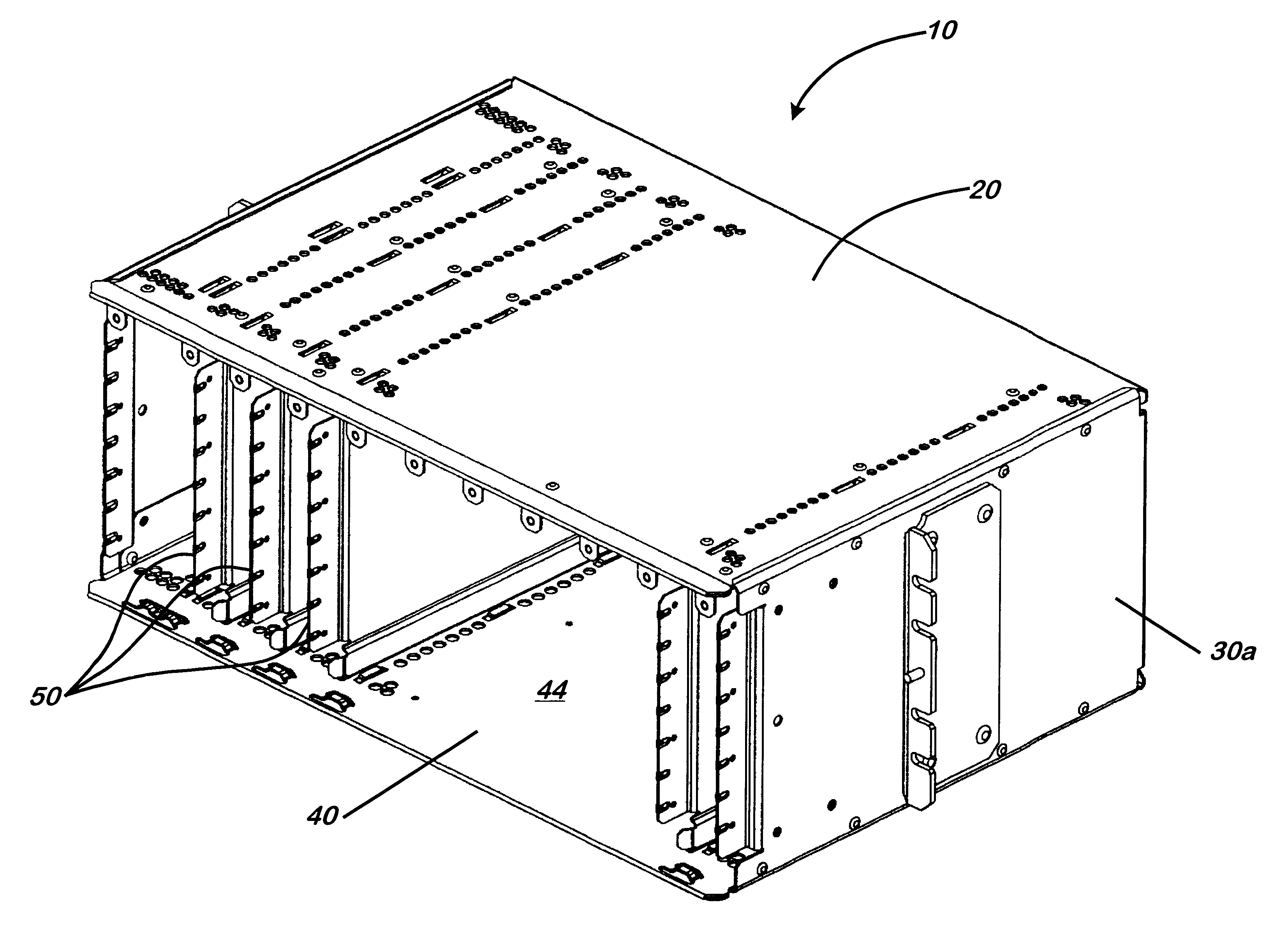
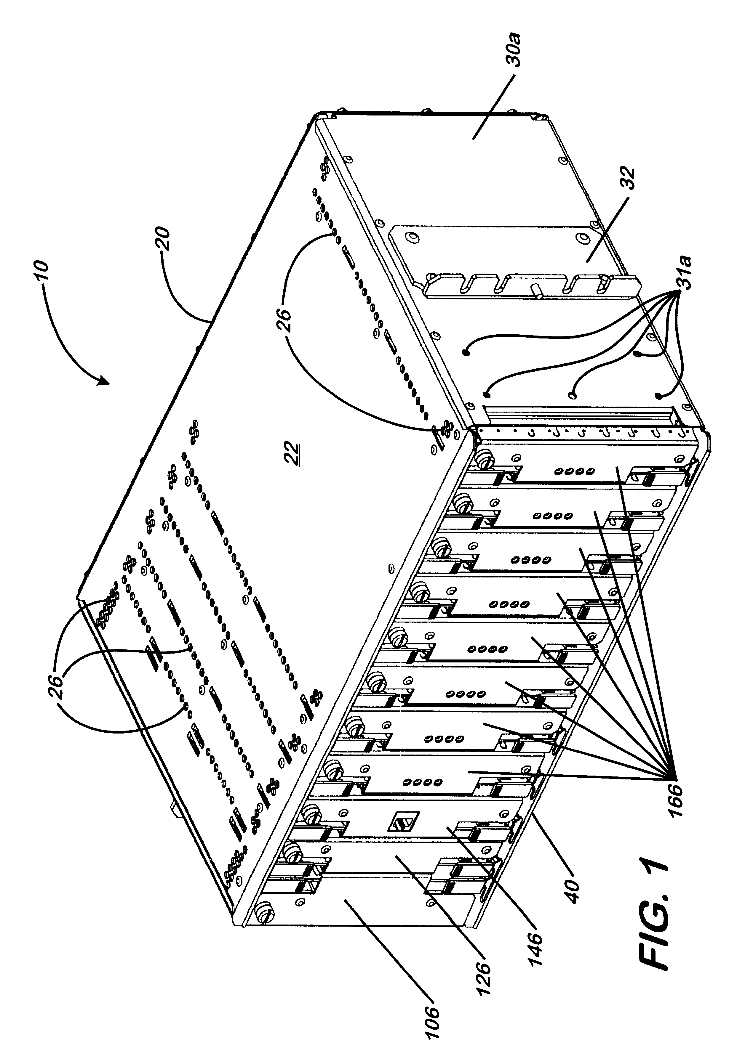
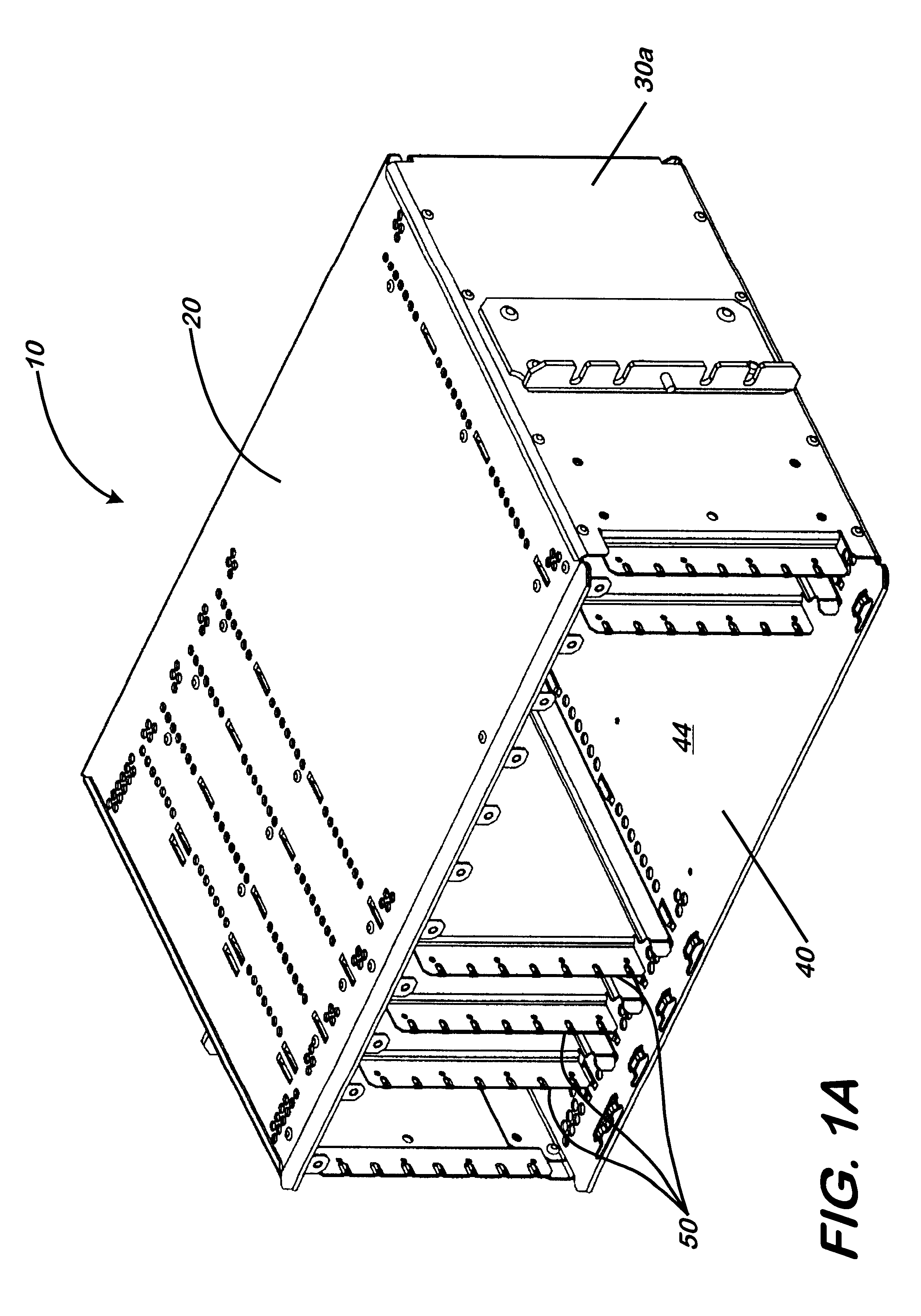
FIG. 1 generally illustrates a fully assembled modem shelf 10 having circuit cards installed in the card slots defined within shelf 10. Shelf 10 could be generally described as a box divided into slots for circuit cards with appropriate connector hardware on the back side of the box. As shown in FIG. 1, shelf 10 comprises among other components, top 20, first side 30a, second side 30b (see, e.g., FIG. 3), bottom 40, back plane assembly 70 and dividers 50 (see, e.g., FIG. 1A). Top 20, sides 30a and 30b, bottom 40, back plate 72 and dividers 50 are stamped from sheet aluminum 5052-H32 about 0.040" thick. When shelf 10 is constructed of...


PUM


Abstract

A modem shelf is described in which internal dividers separate the interior of the shelf into individually isolated Faraday cages that effectively suppress EMI generated by circuit cards mounted within the shelf and isolate the circuit cards from EMI originating outside the shelf and from cards mounted within the shelf. The shelf enables high-speed data communications over a twisted pair network of about 10 Mbps or more. The top and bottom of the shelf are made of relatively thin sheet material, which maximizes the vertical dimension of the circuit cards mounted in the shelf and thus the area on which circuitry can be placed.

Description

I. BACKGROUND OF THE INVENTIONA. Field of the InventionThe present invention relates to a shelf in a relay rack for mounting multiple circuit boards in individual EMI-suppressing card slots. More specifically, the present invention relates to a shelf in a relay rack for mounting a power card, a filter card, a hub card, and multiple modem cards in individual EMI-suppressing card slots.B. Description of the Prior ArtComputer network traffic on LANs and WANs passes at a variety of data transfer rates and through a wide array of equipment including hubs, switches, routers, servers, modems, and filters. A variety of cabling is used to support such traffic, including twisted pair cable, coaxial cable, and fiber optics cable. Each type of cable has advantages and disadvantages.The primary advantage of twisted pair is that it is inexpensive to install and it is already widely installed. Virtually all homes and businesses in the United States have access to plain old telephone service ("POTS...

Claims


Application Information

Patent Timeline
Patent Type & Authority Patents(United States)
IPC IPC(8): H05K9/00H05K7/14
CPCH05K9/0062H05K7/1425
Inventor BEARD, JAMES LAMAR
Owner CIENA
Learn More