

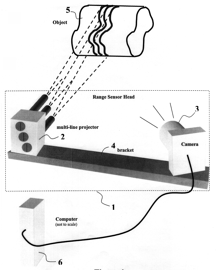
Three-dimensional measurement method and apparatus
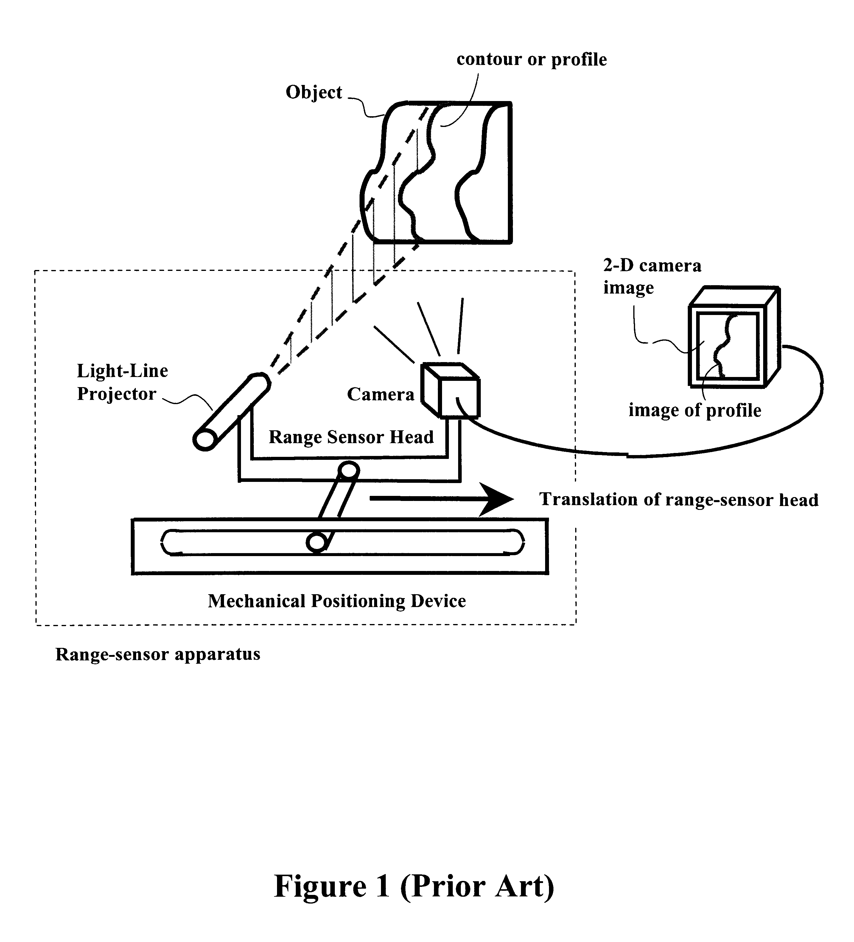
a three-dimensional measurement and apparatus technology, applied in the direction of measuring devices, using optical means, instruments, etc., can solve the problems of inability to move the object relative to a stationary range-sensor head, the inability to carry out the scanning of such objects by moving the range-sensor head, and the inability to move the mechanical positioning device at a single position
- Summary
- Abstract
- Description
- Claims
- Application Information
AI Technical Summary
Problems solved by technology
Method used
Image

Examples
Embodiment Construction
of the Algorithms
The calibration of the range-sensor head, for the preferred embodiment of a light-projector-camera head, is normally performed at the time of manufacturing, although it could be done at any time between measurement sessions, to recalibrate the sensor, as described above. The calibration essentially determines a mapping between a set of 2-D image coordinates corresponding to a set of known 3-D object coordinates. It is used to determine the relationship or mapping of any 2-D image coordinate to a 3-D object coordinate, which will ultimately be used during the 3-D reconstruction in Algorithm 3 described below. The process involves acquisition of 2-D image coordinates corresponding to known points in 3-D space that lie in the planes of the profiles or profile edges (see (1) Knopf, G. and Kofman, J. (1996). Neural Network Mapping of Image-to-Object Coordinates for 3D Shape Reconstruction, in Intelligent Robots and Computer Vision XV: Algorithms, Techniques, A...
PUM
 Abstract
Description
Claims
Application Information