Method and apparatus for increasing bandwidth in sampled systems

a sampled system and bandwidth technology, applied in the field of sampled system bandwidth increase methods and equipment, can solve the problems of inpractical real-time implementation of circuits designed to fix such problems, inability to achieve the effect of real-time implementation, and complicated designs

Inactive Publication Date: 2003-04-01
TELEDYNE LECROY
View PDF3 Cites 38 Cited by
  • Summary
  • Abstract
  • Description
  • Claims
  • Application Information

AI Technical Summary

Benefits of technology

It is therefore an object of the invention to provide an improved Digital Signal Processing (DSP) method and apparatus capa

Problems solved by technology

In many cases, these designs are extremely complicated, particularly in the design of a digital oscilloscope.
What makes things worse is that even upon observing and confirming the existence of problems with the ba

Method used


Image

  • Method and apparatus for increasing bandwidth in sampled systems
  • Method and apparatus for increasing bandwidth in sampled systems
  • Method and apparatus for increasing bandwidth in sampled systems

Examples


Embodiment Construction

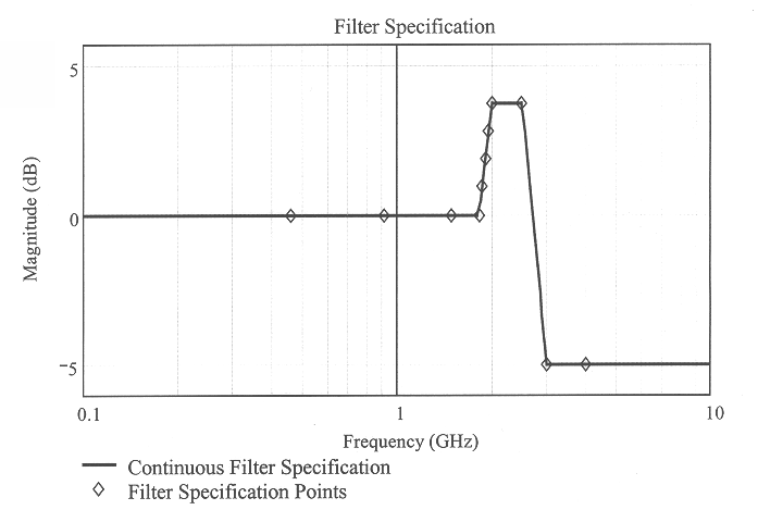
will now be provided, making reference to the figures. In accordance with the invention, given a desired ideal filter specification as shown in FIG. 3, a question arises as to a method for implementation of such an ideal specification in the real world. The preferred approach for such an implementation will now be described.

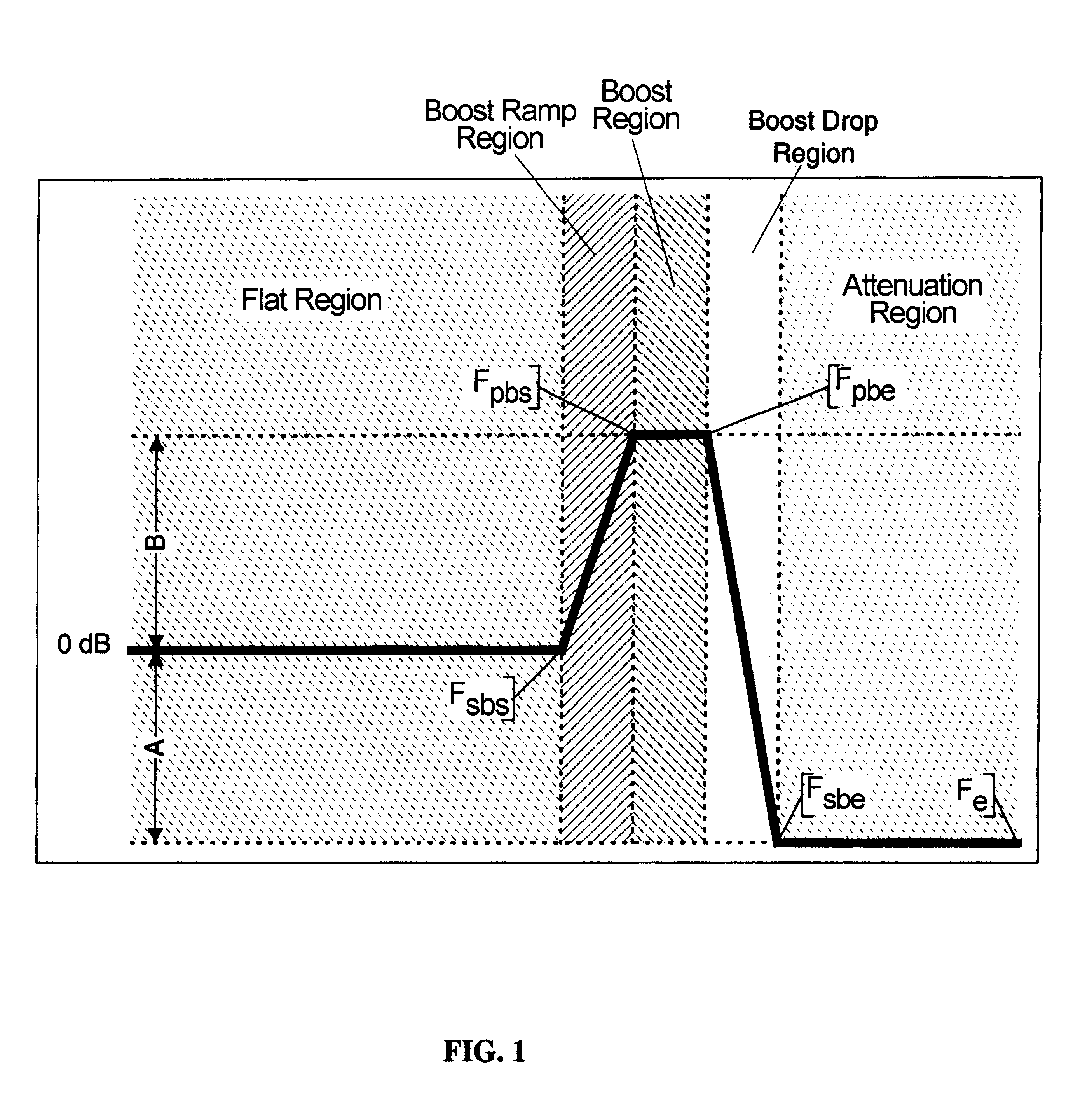
First, applicant introduces some explanation of notation regarding the filter specification:

This notation is shown diagrammatically in FIG. 1.

In order to implement the ideal filter specification of FIG. 3 as an actual physical filter, some of the aspects of the specification should be noted:

1. The system is flat out to F.sub.sbs.

2. There is a sharp corner at F.sub.sbs,

3. There is a rather steep rise in the boost ramp region.

4. During the boost region, the boost is held.

5. The filter provides attenuation in the attenuation region.

In order to realize such a filter, it is natural to consider a filter consisting of a pair of complex conjugate poles, and zeros--a four...


PUM


Abstract

Systems that sample a continuous analog time-domain signal. The invention is particularly applicable to systems whose analog components have a bandwidth limit below that desired or specified. The invention has been created to address particular problems in the design of digital sampling oscilloscopes (DSOs) that require more bandwidth than that which is easily achievable through traditionally analog techniques. A method and apparatus are provided in the form of a digital filter that is capable of surgically increasing the bandwidth of the system beyond the bandwidth achievable in an analog system. Furthermore, it is demonstrated that this system can perform this bandwidth increase without degradation in the time-domain performance of the system such as pulse or step response. In some cases, the time-domain performance is improved by flattening of the frequency response. Additionally, the system, while boosting the bandwidth, is capable of simultaneously removing noise and therefore producing a digitized signal of higher fidelity than that obtained without the filter in place.

Description

This invention related generally to the digital manipulation of a continuous time domain sample that is to be sampled in a digital oscilloscope, and more particularly to a digital filter that is capable of increasing the bandwidth of the sampling system beyond the bandwidth range achievable in an analog system.The present state of the art deals with an attempt to increase bandwidth based upon the assumption that only analog manipulation techniques for modifying a signal to improve the bandwidth characteristics of an apparatus are possible. Other digital techniques are seen as manipulations of the signal that change the output result of the system. This results in a design methodology in which analog design engineers painstakingly design to the best of their ability analog circuitry that has high bandwidth, flat frequency response, good pulse response and is noise-free.In many cases, these designs are extremely complicated, particularly in the design of a digital oscilloscope. Some r...

Claims


Application Information

Patent Timeline
IPC IPC(8): G01R13/00G01R13/02H03H17/02G01R13/22G06F17/10
CPCH03H17/02G01R13/0272
Inventor PUPALAIKIS, PETER J.
Owner TELEDYNE LECROY
Why Eureka
Try Eureka