Transmission system for vehicle

a transmission system and vehicle technology, applied in fluid gearings, transportation and packaging, gearing, etc., can solve the problems of inability to eliminate shift shock, large change of driving force, and difficulty in reducing engine speed quickly and accurately

Inactive Publication Date: 2003-04-08
SUBARU CORP
View PDF4 Cites 16 Cited by
  • Summary
  • Abstract
  • Description
  • Claims
  • Application Information

AI Technical Summary

Benefits of technology

To achieve the object, the automatic transmission system having an input shaft, an output shaft, a plurality of drive gears mounted on the input shaft, a plurality of driven gears mounted on the output shaft and meshing with the drive gears, a torque converter disposed between a crankshaft of an engine and the input shaft, synchromesh mechanisms for synchronously engaging the drive gears with the driven gears and a shift controller for automatically actuating the synchromesh mechanisms so as to obtain a required gear ratio, comprises a lock-up clutch incorporated in the torque converter between the crankshaft and an output element of the torque converter for connecting the crankshaft with the input shaft, an electronically controlled throttle valve for automatically operating to reduce a rotation speed of the crankshaft when the gear is shifted so as to smoothly synchronize the drive gears with the driven gears, a bypass clutch for transmitting torque from the input shaft to the output shaft when the gear is shifted, while the electronically controlled throttle valve operates to reduce a rotation speed of the engine, an input clutch disposed between the output element of the torque converter and the input shaft for selectively controlling a torque transmission from the output element of the torque converter to the input shaft when the gear is shifted, and a brake mechanism disposed on an impeller shell of the torque converter for additionally reducing a rotational speed of the crankshaft while the electronically controlled throttle valve operates to reduce a rotational speed of the crankshaft so as to smoothly and swiftly engage the drive gears with the driven gears.

Problems solved by technology

However, it is difficult to reduce the engine speed swiftly and accurately with the bypass clutch and the engine control using the electronic control throttle valve.
However, in this technology, since a clutch is released to disconnect power transmission from the engine to the input shaft at gearshifting, particularly, when the gear is shifted from the 1.sup.st speed ratio to the 2.sup.nd speed ratio or from the 2.sup.nd speed ratio to the 3.sup.rd speed ratio, the change of driving force is so large that a shift shock can not be eliminated.

Method used


Image

  • Transmission system for vehicle
  • Transmission system for vehicle
  • Transmission system for vehicle

Examples


third embodiment

In case of the transmission system of a third embodiment shown in FIG. 6 and FIG. 7, the brake mechanism 61 is disposed between the stator 49 of the torque converter 6 and the supporting shaft 47 for supporting a reaction torque of the stator 49. The brake mechanism 61 includes a brake drum 82 secured to the supporting shaft 47 through spline fitting and a brake hub 83 fixed to the pump side outer shell 42. Brake driven discs 82a are mounted on the brake drum 82 and brake drive discs 83a are driveably mounted on the brake hub 83. Further, the brake driven discs 82a have contact with the brake drive discs 83a.

A brake piston 84 is slidably incorporated in the brake drum 82. When working fluid is fed to an oil chamber 84a, the brake discs 82a and 83a generate an engagement force. Braking torque of the brake mechanism 61 is regulated by adjusting the engagement force of the brake discs 82a, 83a. The brake piston 84 is subjected to a biasing force in a releasing direction by a spring mem...

fifth embodiment

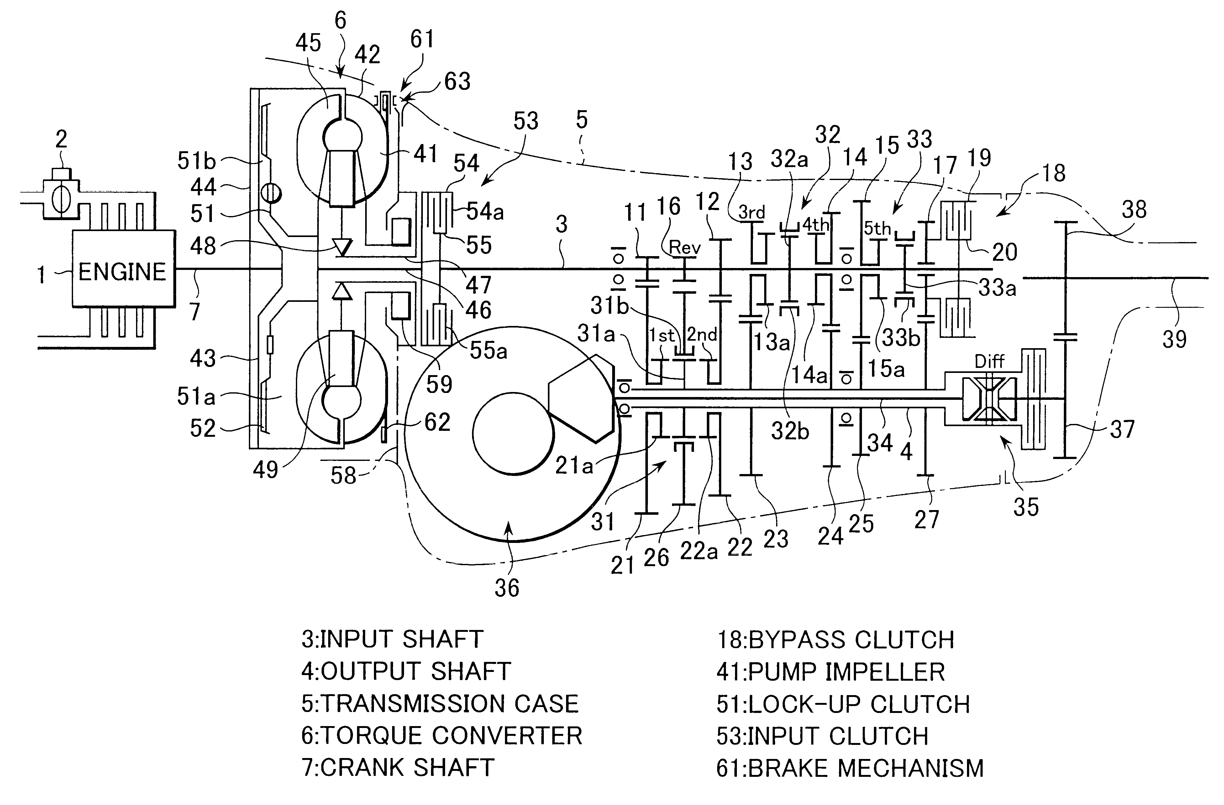
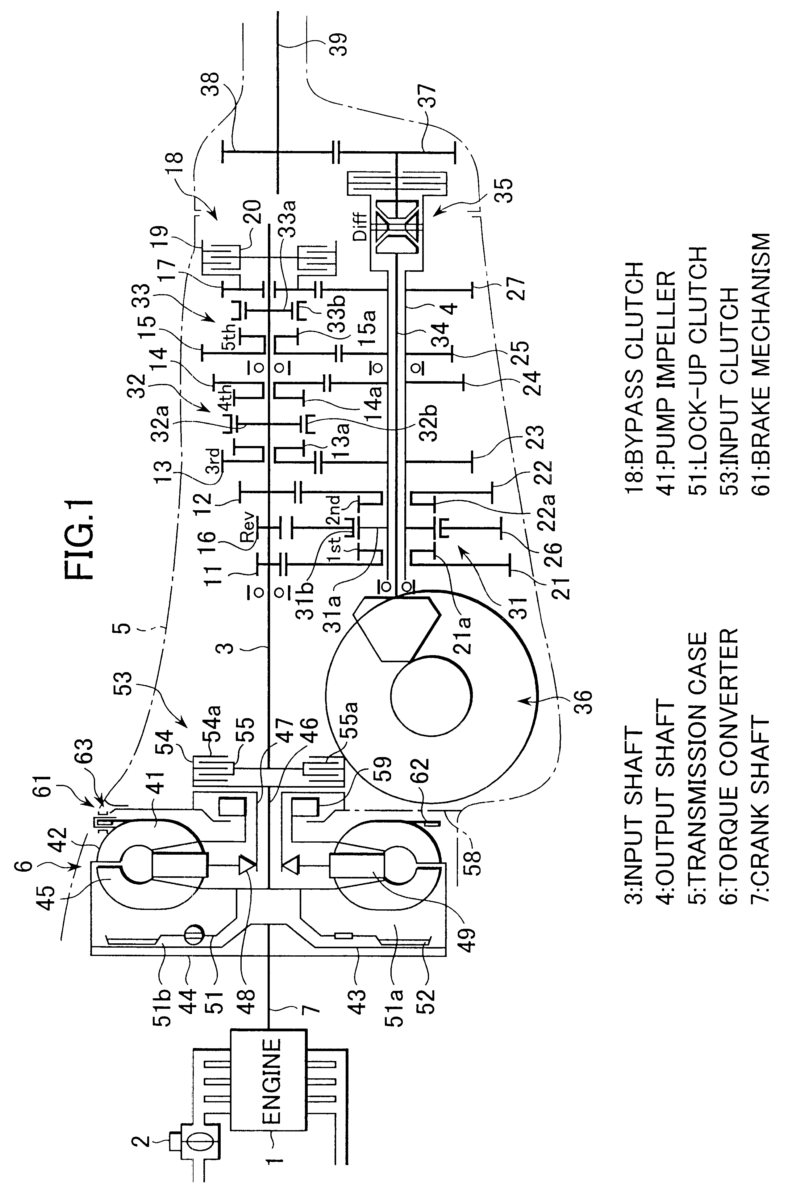
FIG. 9 is a skeleton diagram showing a transmission system.

In this transmission system, the input clutch 53 is disposed between an output element of the turbine runner 45 and an input element of the lock-up clutch 51 in the same manner as in case of FIG. 8 and the brake mechanism 61 is provided on an inner periphery surface of the stator 49 of the torque converter 6.

In these transmission systems shown in FIG. 8 and FIG. 9, since the input clutch 53 and the lock-up clutch 51 are integrally incorporated in the torque converter 6 and the clutch drum of the input clutch 53 is driveably connected with the turbine runner 45, the axial or length of the transmission system can be shortened. As a result, a variety of transmission types, transversely mounted type, longitudinally mounted type and the like, can introduce these transmission systems.

The transmission systems described before in the second, third, fourth and fifth embodiments have automatic transmissions comprising the torque conve...

sixth embodiment

FIG. 10 shows a transmission system according to a The transmission system comprises a flywheel dumper 90, an input clutch 53, a brake mechanism 61, a plurality of shift gear trains and a bypass clutch 18, not including a torque converter.

As shown in FIG. 10 and FIG. 11, the flywheel dumper 90 comprises a drive plate 91 driveably secured to the crankshaft 7 and a driven plate 93 connected with the drive plate through a spring member 92 for absorbing shocks. The driven plate is spline-fitted over a rotation shaft 94 which is rotatably supported by the supporting wall 58 of the transmission case 5.


PUM


Abstract

An automatic transmission system for a vehicle having a plurality of drive gears mounted on an input shaft, a plurality of driven gears mounted on an output shaft and meshing with the drive gears, a torque converter disposed between a crankshaft of an engine and the input shaft, synchromesh mechanisms for synchronously engaging the drive gears with the driven gears and a shift controller for automatically actuating the synchromesh mechanisms so as to obtain a required gear ratio, includes a lock-up clutch incorporated in the torque converter for connecting a turbine shaft of the torque converter with the crankshaft, an electronically controlled throttle valve for automatically operating to reduce a rotation speed of the crank shaft when the gear is shifted, a bypass clutch for transmitting torque from the input shaft to the output shaft when the gear is shifted while the electronically controlled throttle valve operates to reduce a rotation speed of the crankshaft, an input clutch provided between an output element of the torque converter and the input shaft for selectively controlling a torque transmission from the crankshaft to the input shaft when the gear is shifted, and a brake mechanism provided on an impeller shell of the torque converter for additionally reducing a rotational speed of the crankshaft while the electronically controlled throttle valve operates to reduce a rotational speed of the crankshaft.

Description

1. Field of the InventionThe present invention relates to a transmission system for a vehicle and more particularly to an automatic transmission whose gear trains are originated from those of a conventional manual transmission.2. Discussion of Prior ArtGenerally, a manual transmission, in which the gear is manually shifted, has an input shaft directly connected to an engine and having a plurality of drive gears and has an output shaft having a plurality of driven gears paired with the drive gears and connected to drive wheels. That is, there are provided a plurality of shift gear trains between the input shaft and the output shaft. When gear is changed, after a clutch is disengaged, changeover mechanisms such as synchromesh mechanism are manually operated to change over paired shift gear trains and then the clutch is engaged. This sequence of manual operations accomplishes a gear shift of a vehicle.The manual transmission can be converted into an automatic transmission by replacing ...

Claims


Application Information

Patent Timeline
Patent Type & Authority Patents(United States)
IPC IPC(8): F16H61/04F16H61/14F16H3/08F16H3/12B60W10/06B60W30/18F16H47/00
CPCB60W30/18F16H3/12F16H61/0403F16H61/143B60K2741/065B60W2710/1011Y10T477/6337F16H2061/0407F16H2061/0411Y10T74/19149Y10T477/6333Y10T477/677F16H2003/123B60W10/04B60W10/11B60W30/1819
Inventor KOBAYASHI, TOSHIO
Owner SUBARU CORP
Why Eureka
Try Eureka