Valve for controlling liquids

a valve and valve body technology, applied in the direction of valve operating means/release devices, fuel injecting pumps, machines/engines, etc., can solve the problems of system pressure, drop, and undetected valve leakage loss, and the efficiency of the entire system is sharply reduced

Inactive Publication Date: 2003-04-15
ROBERT BOSCH GMBH
View PDF8 Cites 14 Cited by
  • Summary
  • Abstract
  • Description
  • Claims
  • Application Information

AI Technical Summary

Benefits of technology

The valve for controlling fluids of the invention having the characteristics of claim 1 has the advantage that the gap between the solid body and the valve body can be designed as relatively large, so that an adequate volumetric throughput is assured even at very low temperatures of the flowing fluid. At rising temperature and decreasing viscosity of the fluid flowing through the gap, the solid body expands more, because of its higher coefficient of thermal expansion, than does the material of the valve body, so that with increasing temperature the gap decreases in size, and thus advantageously the entire volumetric throughput is adjusted at medium and high temperatures in the same way as in the low temperature range.Since with the valve of the invention an increase in the leakage rate in the low-pressure region as a consequence of rising temperatures is prevented, the necessity of bleeding off large amounts of excess pumped fluid through an overpressure valve is also dispensed with, and the efficiency of the entire system is therefore unimpaired.Further advantages and advantageous features of the subject of the invention can be learned from the specification, drawing and claims.

Problems solved by technology

In the low-pressure region, in particular the hydraulic coupler, the hydraulic system requires a system pressure, which drops because of leakage if adequate refilling with hydraulic fluid is not done.
However, the dimensioning of the leakage gap is a problem; this gap must be adjusted such that the system pressure in the entire operating region can be built up and maintained on the low-pressure side of the valve.
Thus an undesirably great leakage loss of the valve exists, and because of this the efficiency of the entire system drops sharply.

Method used


Image

  • Valve for controlling liquids
  • Valve for controlling liquids
  • Valve for controlling liquids

Examples


Embodiment Construction

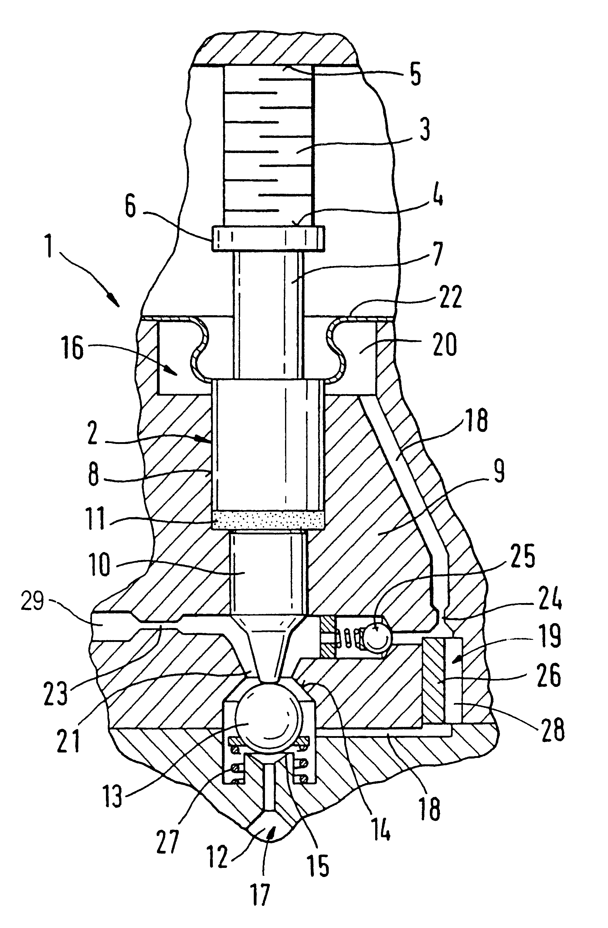
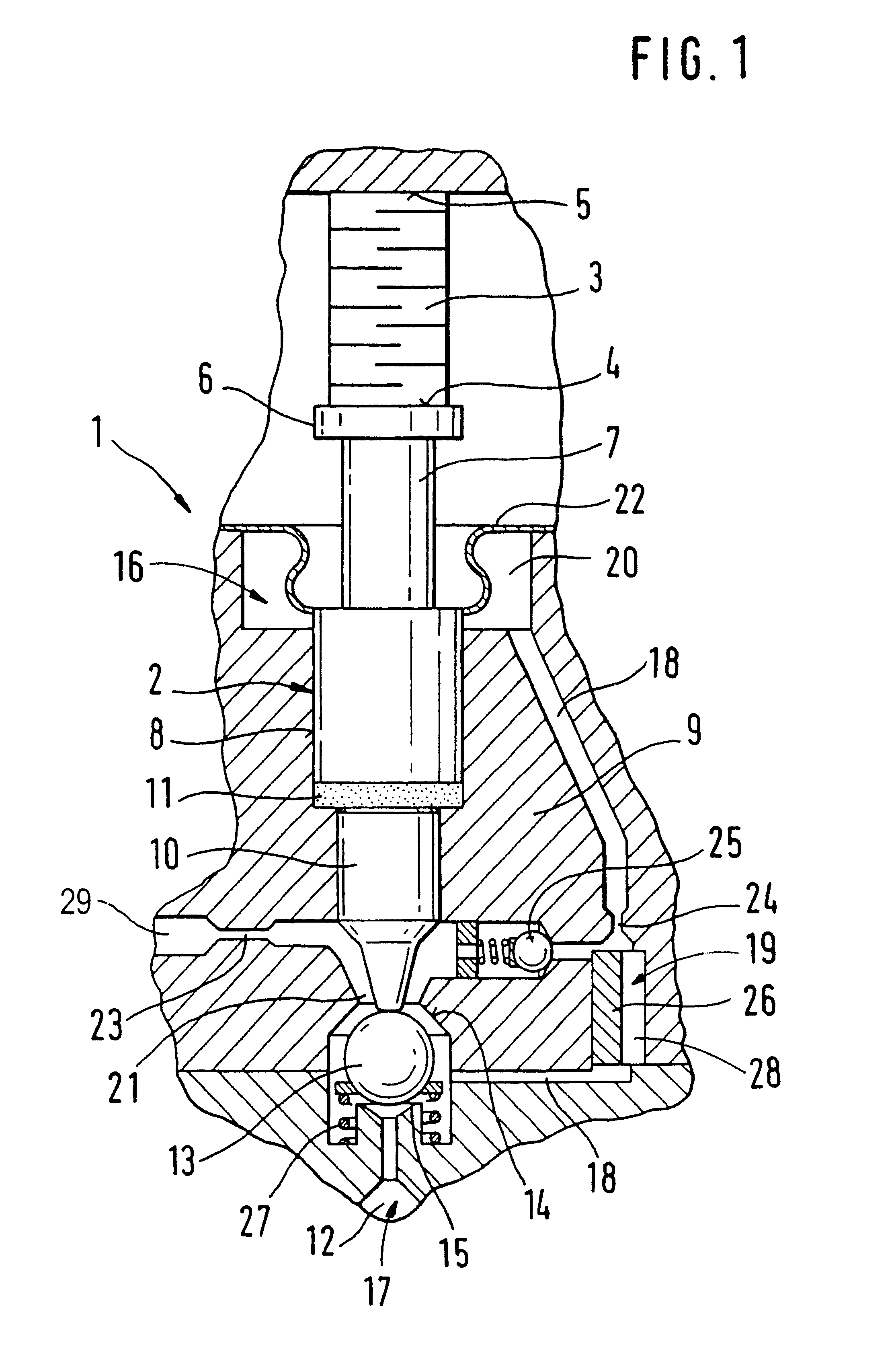
The exemplary embodiment shown in FIG. 1 illustrates a use of the valve of the invention in a fuel injection valve 1 for internal combustion engines of motor vehicles. The fuel injection valve 1 is embodied here as a common rail injector, and the fuel injection is controlled via the pressure level in a valve control chamber 12, which is connected to a high-pressure supply.

The injection onset, injection duration, and injection quantity are adjusted in the fuel injection valve 1 via fuel ratios; a valve member 2 is triggered via an actuator system, embodied as a piezoelectric unit with a piezoelectric actuator 3, that is disposed on the side of the valve member 2 remote from the valve control chamber and the combustion chamber. The piezoelectric actuator 3 is made up in the usual way of multiple layers, and on its side toward the valve member 2 it has an actuator head 4 and on its side remote from the valve member it has an actuator foot 5, which is braced on a wall of a valve body 9....


PUM


Abstract

A valve for controlling fluids is described, wherein a valve closing member (13) divides a low-pressure region (16) in the valve (1) from a high-pressure region (17), and a filling device (19) is provided to compensate for a leakage quantity from the low-pressure region (16) by withdrawal of hydraulic fluid from the high-pressure region (17). The filling device (19) is embodied in a valve body (9) with a conduitlike hollow chamber (18) in which a solid body (26) is disposed in such a way that a gap (28) is formed between the solid body (26) and the valve body (9). The material of the solid body (26) has a coefficient of thermal expansion that is so much greater than that of the material of the valve body (9) that with increasing temperature, a viscosity-dictated increase in the volumetric flow around the solid body (26) is at least partly limited (FIG. 1).

Description

PRIOR ARTThe invention is based on a valve for controlling fluids of the type defined in greater detail in the preamble to claim 1.In the industry, valves for controlling fluids are well known in which a valve closing member divides a low-pressure region in the valve from a high-pressure region, for instance in pumps or fuel injectors in motor vehicles.European Patent Disclosure EP 0 477 400 A1 also describes such a valve, which is actuatable via a piezoelectric actuator and has an arrangement for a travel converter, acting in the direction of reciprocation, of the piezoelectric actuator; in this arrangement, the deflection of the actuator is transmitted via a hydraulic chamber, which functions as a hydraulic step-up means or coupling and tolerance compensating element. The hydraulic chamber encloses a common compensation volume between two pistons defining this chamber, of which one piston is embodied with a smaller diameter and is connected to a valve member to be triggered, and t...

Claims


Application Information

Patent Timeline
Patent Type & Authority Patents(United States)
IPC IPC(8): F02M59/46F02M59/00F16K31/00F02M47/02F02M47/00F02M51/00F02M61/16F02M61/20F16K31/64
CPCF02M47/027F16K31/007F02M63/0026
Inventor HEINZ, RUDOLFSTOECKLEIN, WOLFGANGSCHMOLL, KLAUS-PETER
Owner ROBERT BOSCH GMBH
Why Eureka
Try Eureka