
Method for producing honeycomb sandwich panel

a honeycomb and sandwich panel technology, applied in the field of honeycomb sandwich panel production, can solve the problems of reducing the product cost and weight, affecting reducing the production efficiency of honeycomb sandwich panels, so as to achieve the effect of reducing the cost and weight of products and simplifying the production steps

Inactive Publication Date: 2003-04-22
HONDA PATENTS & TECH NORTH AMERICA
View PDF3 Cites 46 Cited by
  • Summary
  • Abstract
  • Description
  • Claims
  • Application Information

AI Technical Summary

Benefits of technology

Thus, the object of the present invention is to provide a method for producing a honeycomb sandwich panel suited for the production of a panel structure having a curved surface while preventing the crush of a honeycomb core, thereby achieving simplification of the production steps and reduction in product cost and weight.
As a result of intensive research in view of the above object, the inventors have found that a honeycomb sandwich panel constituted by a pair of prepreg laminate skins and a honeycomb core interposed between the skins can be produced without crushing the honeycomb core by using flat plate-shaped elastic jigs and flat plate-shaped press jigs during pressurization, or by making wider a portion of the panel where a pair of prepreg laminate skins are overlapping each other. The present invention has been completed based on this finding.

Problems solved by technology

In this production method, however, the edge of the honeycomb core is unable to withstand the forming pressure applied, resulting in frequent deformation (crush) of the edge.
In this method using a forming die having projections, however, the projections are dangerous to an operator; the forming operation is troublesome because periodic cleaning and repair for projections are necessary; and the projections become an obstacle in sealing the forming die with a vacuum bag.
None of these methods, however, is practical because of the problems such as increased number of steps, increased cost for forming, or the like.
In this method, however, widening of filling area for the prevention of crush invites increased panel weight, against the aim of lighter product weight.
Moreover, because the cured filler is hard and fragile, the honeycomb sandwich panel produced may suffer cracking when the panel has a curved surface.
The forming pressure lower than usual (about 6 kgf / cm.sup.2), however, tends to invite insufficient forming owing to pressure shortage in portions of skins where no honeycomb core is interposed.

Method used


Image

  • Method for producing honeycomb sandwich panel
  • Method for producing honeycomb sandwich panel
  • Method for producing honeycomb sandwich panel

Examples


Embodiment Construction

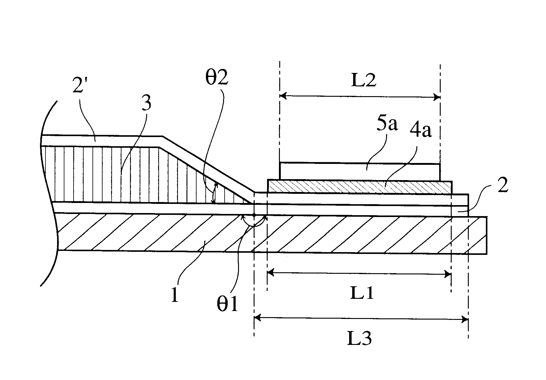
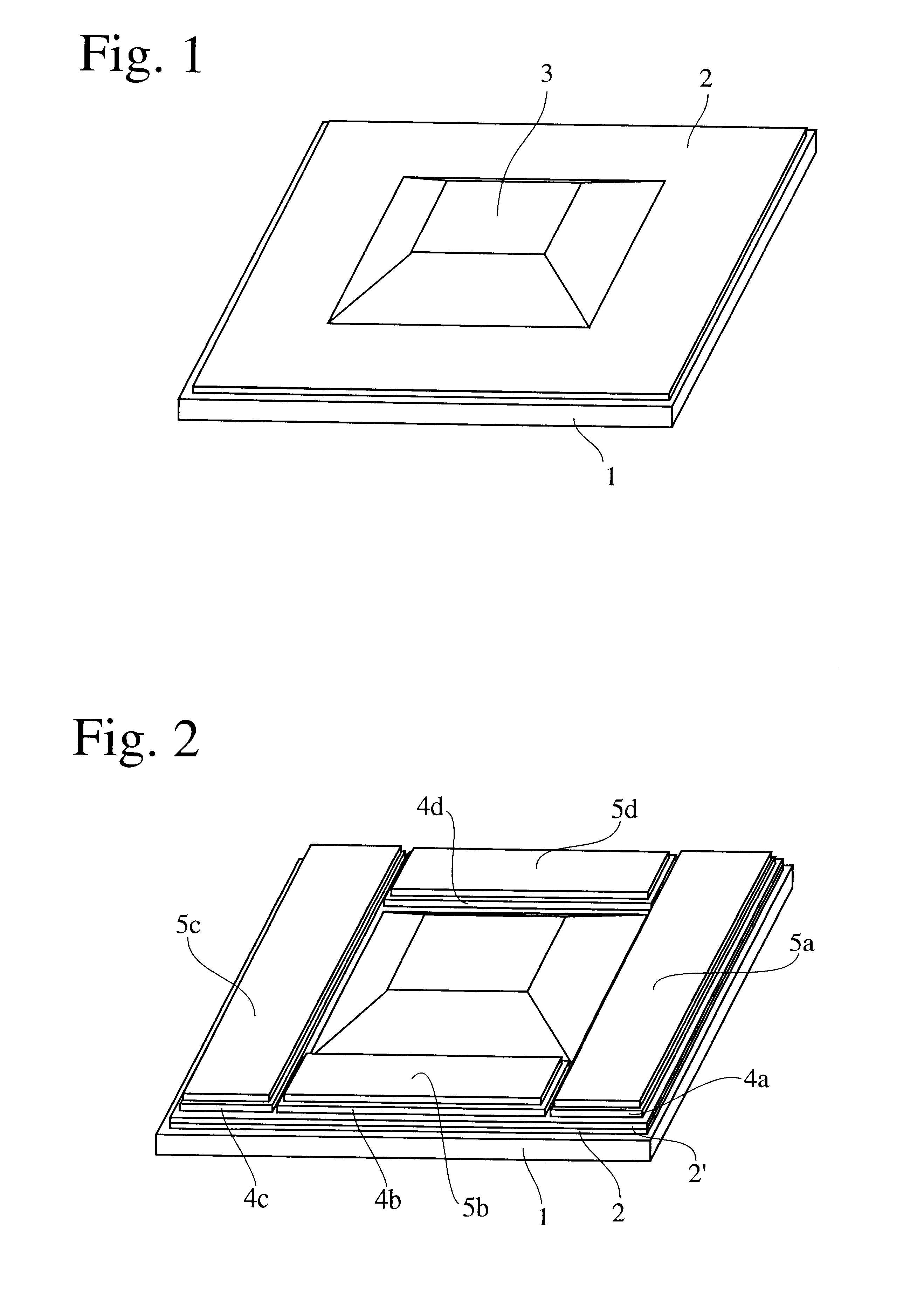
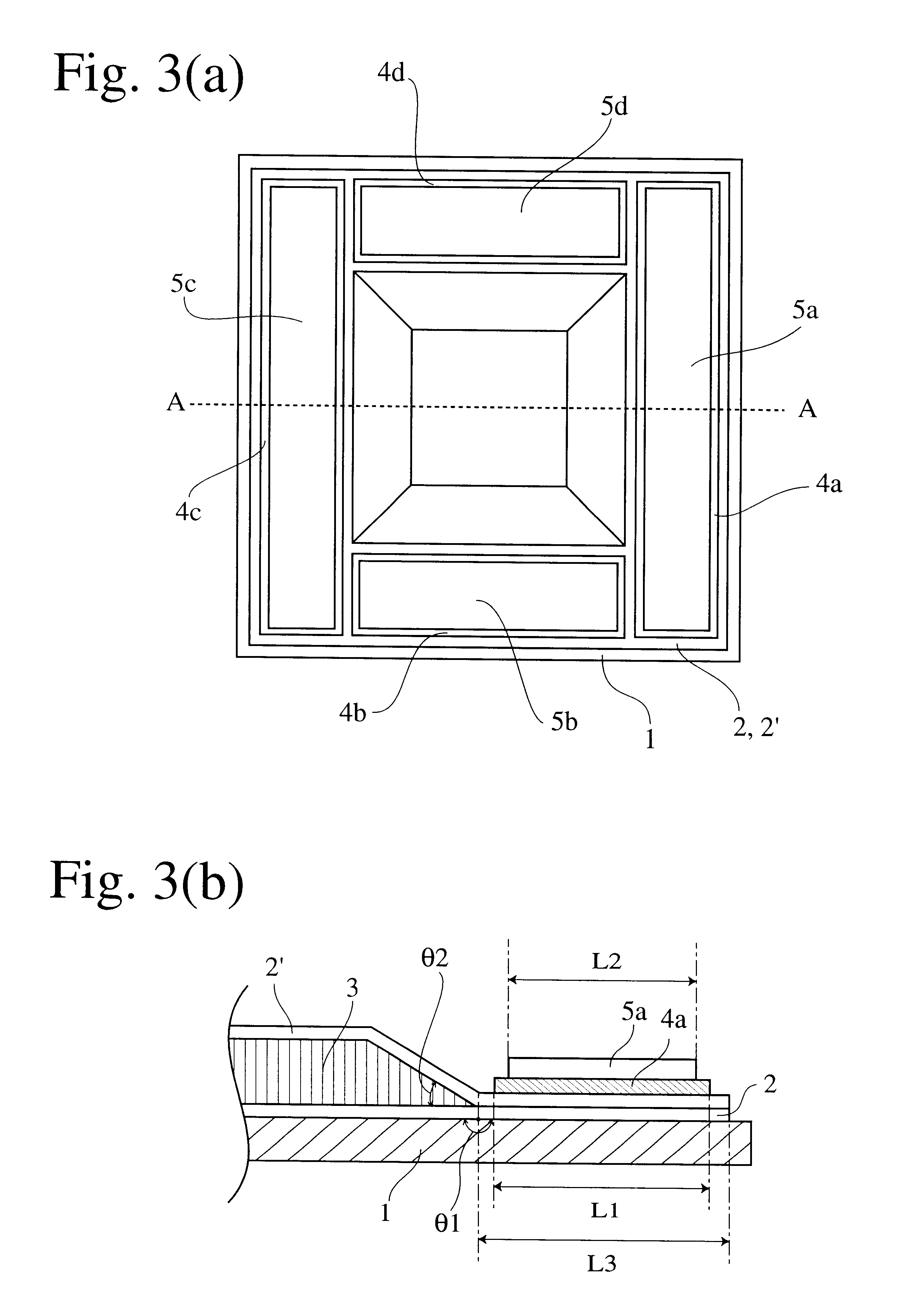
The method for producing a honeycomb sandwich panel according to the present invention will be explained hereinafter with reference to FIGS. 1 to 9. FIGS. 1 and 2 are perspective views each showing an example of the first production method of the present invention. FIG. 3(a) is a top view of FIG. 2, and FIG. 3(b) is a fragmentary sectional view taken along the line A--A in FIG. 3(a).

In the first method of the present invention, a honeycomb core 3 is mounted on a first prepreg laminate 2 (for an outer skin) placed on a forming die 1 as shown in FIG. 1. As shown in FIG. 2, a second prepreg laminate 2' (for an inner skin) is then superimposed thereon to cover the honeycomb core 3. On the portion of the resulting assembly where the prepreg laminates 2 and 2' are overlapping each other are mounted flat plate-shaped elastic jigs 4a, 4b, 4c and 4d. With flat plate-shaped press jigs 5a, 5b, 5c and 5d superimposed thereon, the assembly of the first prepreg laminate 2, the honeycomb core 3 an...


PUM

PropertyMeasurementUnit
pressureaaaaaaaaaa
thicknessaaaaaaaaaa
widthaaaaaaaaaa

Abstract

A honeycomb sandwich panel is produced by (a) mounting a honeycomb core on a lower prepreg laminate skin placed on a forming die, (b) superimposing thereon an upper prepreg laminate skin to cover the honeycomb core, (c) mounting flat plate-shaped elastic jigs on a portion of the resulting assembly where the lower prepreg laminate skin and the upper prepreg laminate skin are overlapping each other, (d) superimposing flat plate-shaped press jigs on the elastic jigs, and (e) heating the assembly under pressure for adhesion forming.

Description

The present invention relates to a method for producing a honeycomb sandwich panel suited for the production of a panel structure having a curved surface; particularly to a method for producing a honeycomb sandwich panel while preventing a honeycomb core from crushing, thereby simplifying the production process and thus reducing the cost and weight of the product.Honeycomb sandwich panels constituted by a pair of prepreg skins and a honeycomb core interposed between the skins are light in weight and superior in strength and rigidity; therefore, they are used as structural members of aircraft, automobiles, etc. These honeycomb sandwich panels are generally produced by first cutting a honeycomb material into a desired shape to form a honeycomb core, covering both sides of the honeycomb core with prepreg laminate skins, mounting the resulting assembly on a forming die, if necessary, with an adhesive between the honeycomb core and the prepreg laminate, and heating the assembly under pre...

Claims


Application Information

Patent Timeline
Patent Type & Authority Patents(United States)
IPC IPC(8): B29C70/04B29C70/08B29C70/44B29D24/00B32B3/12B32B3/02B32B5/28
CPCB29C70/088B29D24/007B29C70/44Y10T428/24149
Inventor SATO, KEIICHIKASAHARA, YUKINASU, MAKOTO
Owner HONDA PATENTS & TECH NORTH AMERICA
Learn More