Installation structure for optical fiber

a technology of optical fibers and installation structures, which is applied in the direction of optics, instruments, optical light guides, etc., can solve the problems of too large area, risk of floating or bending of optical fibers, and difficulty in installing plurality of optical fibers in the same precision on a plurality of v-shaped grooves

Inactive Publication Date: 2003-04-22
NEC CORP
View PDF13 Cites 55 Cited by
  • Summary
  • Abstract
  • Description
  • Claims
  • Application Information

AI Technical Summary

Benefits of technology

It is another object of the present invention to provide an installation structure which can suppress a floating or a bending of the optical fiber due to its elasticity and which enables the whole periphery of the optical fiber to be fixed, for achieving the installation of the optical fiber in high precision, with high strength and with high reliability.
Since the V=shaped groove is divided into the positioning section and the alignment fixing section, the outer peripheral of the optical fiber comes into contact with only the positioning section to place it at a predetermined position and is not in contact with the alignment fixing section. Therefore, it is possible to fix the optical fiber with a fixing agent in the alignment fixing section and to minimize the length of the positioning section.

Problems solved by technology

Therefore, too much large area is required for contacting the groove surface of the V-shaped groove with the optical fiber, and there has been a risk of an occurrence of a floating or a bending of the optical fiber due to the elasticity of the optical fiber depending on an installation angle, a pressing force and a pressing method at the time of installing the optical fiber.
Because of the above reason, according to the conventional installation structure for an optical fiber, it has been difficult to install a plurality of optical fibers in the same precision on a plurality of V-shaped grooves.
In other words, it has been difficult to position optical fibers in alignment in high precision with satisfactory reproducibility.
However, the prior-art installation structure has not been able to meet sufficiently such requirement for high-precision installation.
Therefore, it is structurally impossible to fix the whole periphery of an optical fiber based on the prior-art installation structure.
As a result, according to the prior-art installation structure for an optical fiber, the fixing strength of an optical fiber is not sufficient and there has been a possibility of a deviation or dropping of the optical fiber.
Further, according to the prior-art installation structure for an optical fiber based on a fixing system using a pressing plate, at the time of fixing the pressing plate to the V-shaped groove substrate with a fixing agent such as a resin, a solder or the like, it is not possible to prevent this fixing agent from flowing into the V-shaped groove where the optical fiber is going to be positioned.
The flow of the fixing agent into the V-shaped groove possibly causes a floating and a positions deviation of the optical fiber.

Method used


Image

  • Installation structure for optical fiber
  • Installation structure for optical fiber
  • Installation structure for optical fiber

Examples


first embodiment

the present invention will be described in detail with reference to FIGS. 1 to 3, taking as an example an application to an optical coupler for coupling a light-emitting source and an optical fiber.

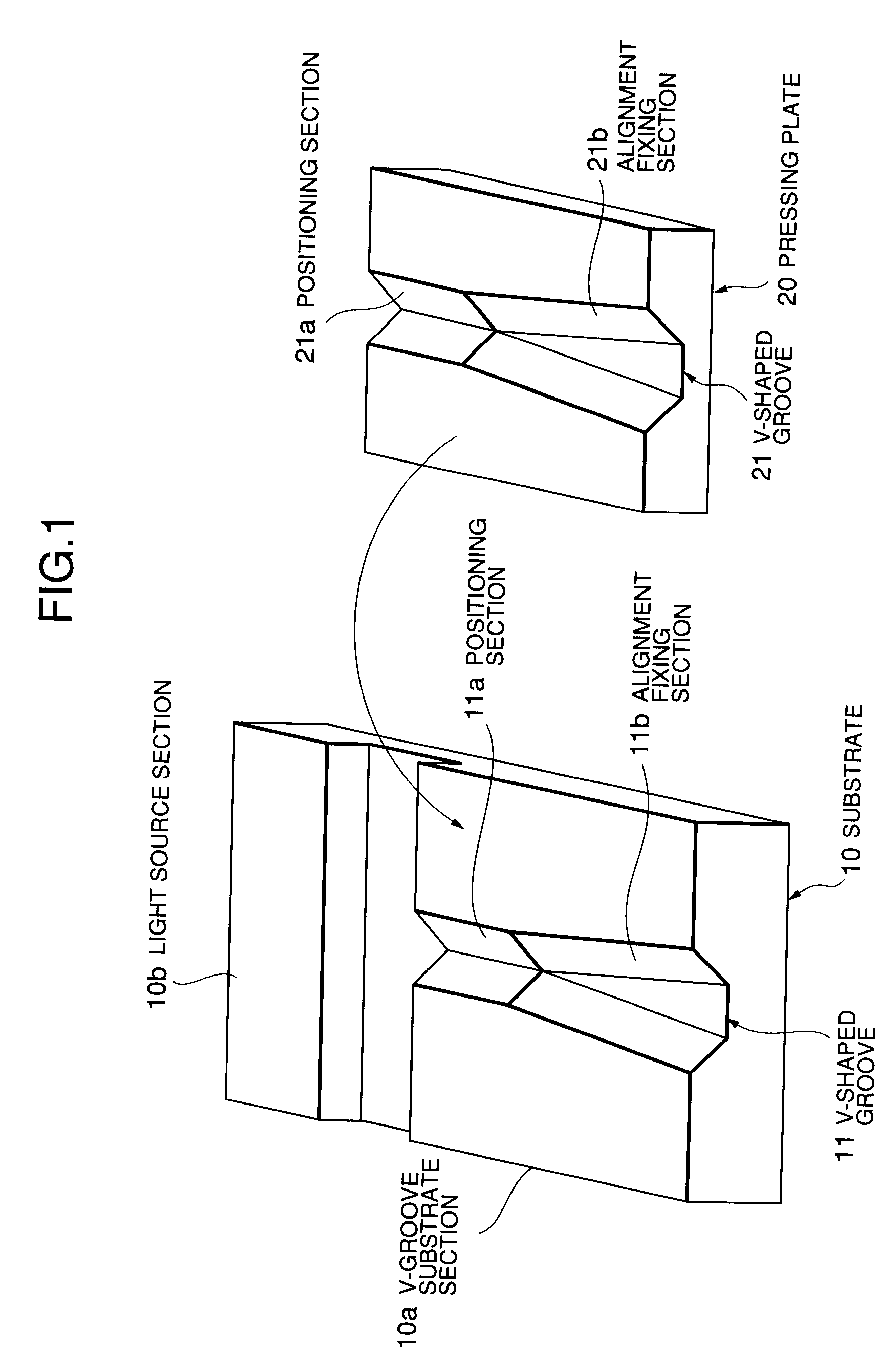
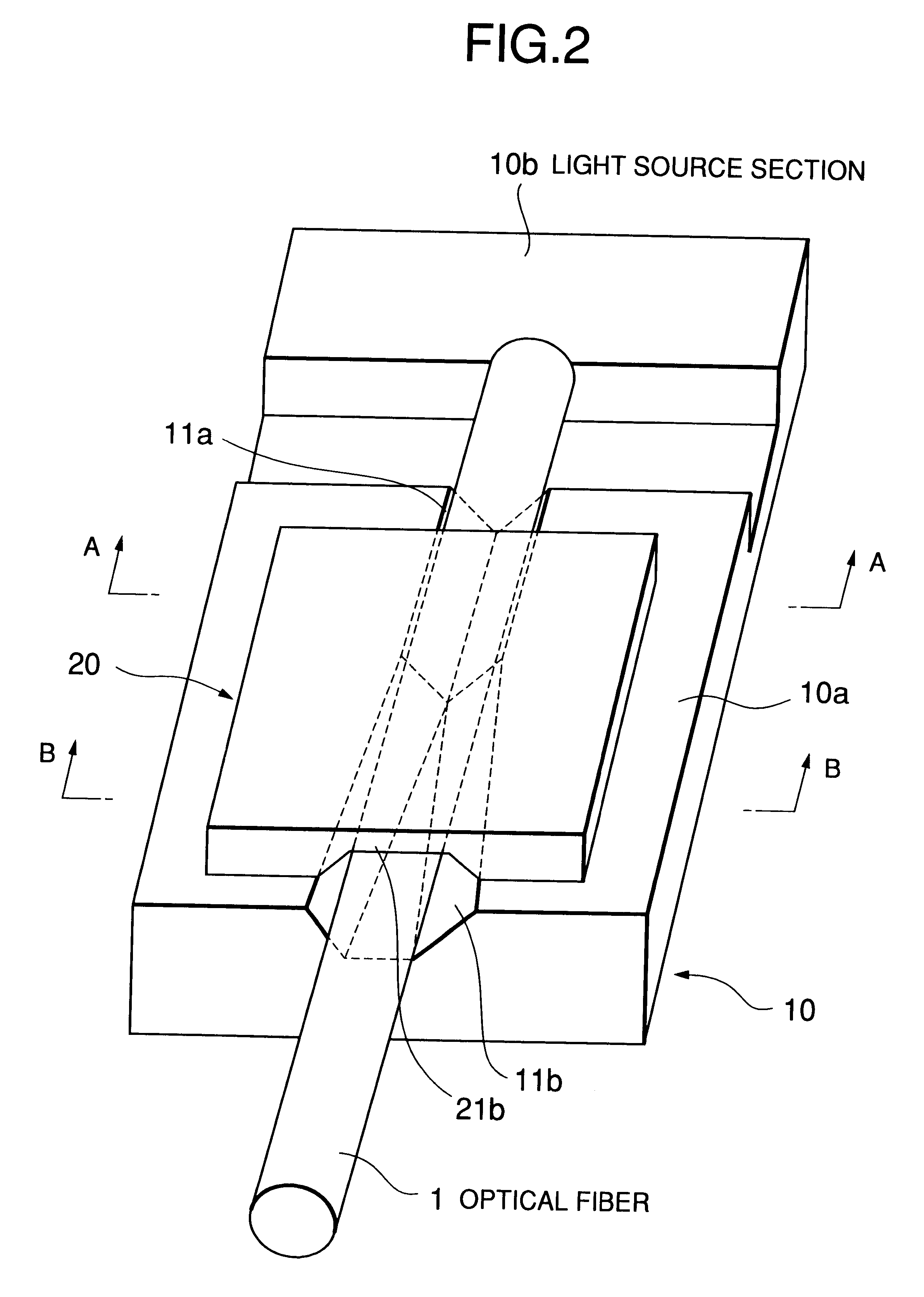
Referring to FIG. 1, a substrate 10 is made of silicon, for example. On one surface (an upper surface in the example shown) of the substrate 10, a v-groove substrate section 10a and a light source section 10b arc formed integrally with a groove provided therebetween.

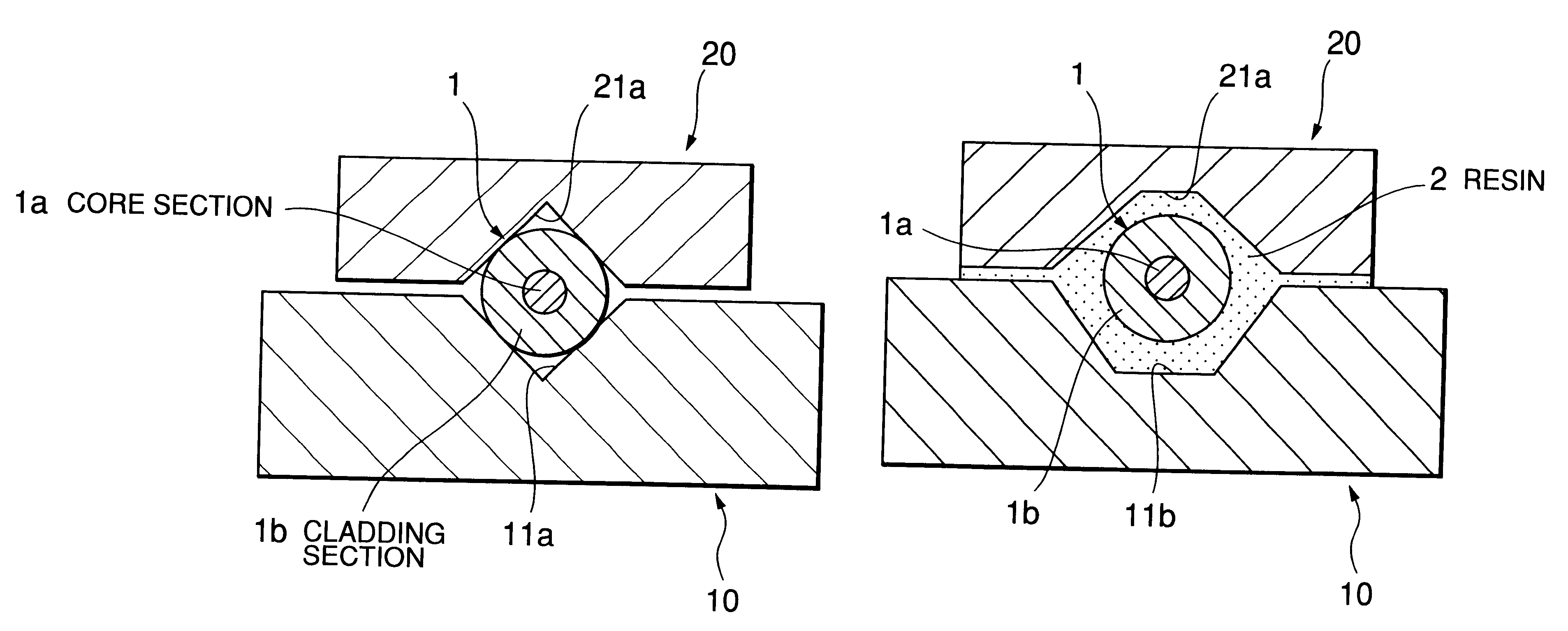
On the upper surface of the V-groove substrate section 10a, there is formed a v-shaped groove 11 having approximately a v-shaped cross-section traversing in a longitudinal direction, with the v-shaped groove 11 opening on both end surfaces of the v-groove substrate section 10a. In the illustrated example, the v-shaped groove 11 is formed toward a light emitting element provided in the light source section 10b, and this direction is almost parallel with an optical axis of the light emitting element. In the illustrated example, ...

second embodiment

In FIG. 4, an application to an optical communication module similar to the above-described first embodiment is shown. In other words, a V groove substrate section 15a and a light source section 15b are formed together on a substrate 15, in a manner similar to the first embodiment. The second embodiment is different from the first embodiment in that a plurality of slits 12 extending to a V-shaped groove 11 are formed on the upper surface of the V-groove substrate section 15a. Other constituent parts are identical with those of the first embodiment, which are denoted by the same reference numbers and their detailed explanation are omitted.

Referring to FIG. 4, the slits 12 are formed in a comb shape on both sides sandwiching the V-shaped groove 11,, each of the slits 12 extending to the V-shaped groove 11. These slits 12 can be formed by etching or by mechanical processing in a manner similar to the forming method of the V-shaped groove 11 explained in the first embodiment.

According t...

third embodiment

In FIG. 5, an application to a ferrule type connector is shown as a third embodiment of the present invention.

A V-groove substrate 30 is a silicon substrate. On this V-groove substrate 30, there is formed a V-shaped groove 31 composed of a positioning section 31a and alignment fixing sections 31a and 31c, wherein the positioning section 31a is disposed between the two alignment fixing sections 31b and 31c, these positioning section 31a and alignment fixing sections 31b and 31c are formed on the substrate 30 by etching or by mechanical processing in a similar manner to the above-described two embodiments.

Each of two optical fibers 1 disposed on the V-shaped groove 31 is wound with a ferrule 1c on the outer periphery of an end portion. When the two optical fiber 1 are disposed on the V-shaped groove 31, the positioning section 31a becomes in contact with a part of the outer periphery of the ferrule 1c wound around the end portion of each optical fiber 1 and positions these optical fib...


PUM


Abstract

An installation structure for positioning and holding an optical fiber by means of a V-shaped groove formed on a substrate is disclosed. The V-shaped groove is divided into a positioning section and an alignment fixing section. The positioning section has groove width and depth for allowing the optical fiber to have a contact therewith. The alignment fixing section has groove width and depth larger than those of the positioning section to an extent for not allowing the optical fiber to have a contact therewith, when the optical fiber is disposed on the V-shaped groove.

Description

1. Field of the InventionThe present invention relates to installation technique for optical fibers, and in particular to an installation structure having a V-shaped groove for placing an optical fiber.2. Description of the Related ArtThere has been known an installation structure having a V-shaped groove for placing an optical fiber at a predetermined position and a pressing plate covered on the optical fiber to fix it in the V-shaped groove, thereby to position and hold the optical fiber with no adjustment. Accordingly, such an installation structure has been widely employed in the field of a device requiring the installation of an optical fiber with no adjustment, for example, in an optical communication module for optically coupling an optical fiber with a light-emitting device used as a light source, or in an optical connector for optically connecting optical fibers with each other, or the like. As a structure for connecting optical fibers with each other, there has been known ...

Claims


Application Information

Patent Timeline
Patent Type & Authority Patents(United States)
IPC IPC(8): G02B6/42G02B6/38G02B6/36G02B6/24
CPCG02B6/255G02B6/3652G02B6/423G02B6/3692G02B6/4239G02B6/4233G02B6/4238G02B6/3873
Inventor GOTO, AKIO
Owner NEC CORP
Why Eureka
Try Eureka