Network transceiver for steering network data to selected paths based on determined link speeds

a network transceiver and network data technology, applied in data switching networks, instruments, baseband system details, etc., can solve problems such as inability to communicate with repeaters or switches, and unsuitable operating environments

Inactive Publication Date: 2003-04-29
GLOBALFOUNDRIES INC
View PDF15 Cites 33 Cited by
  • Summary
  • Abstract
  • Description
  • Claims
  • Application Information

AI Technical Summary

Benefits of technology

In accordance with another aspect of the invention, a repeater em comprises first and second repeater interfaces outputting network data at respective data rates, and a network transceiver. The network transceiver is configured for supplying the network data to at least one link partner via a corresponding network medium. The network transceiver includes a multiplexer circuit for supplying the network data between a selected one of the first and second repeater interfaces and the link partner according to a determined link speed of the link partner. Hence, the link partner is automatically connected to the appropriate repeater based on the determined link speed, enabling different speed network nodes to be connected by the network transceiver.
Still another aspect of the invention provides a method of supplying network data between repeater interfaces having respective data rates a network medium providing communication for a link partner. The method comprises determining a link speed of the link partner on the network medium, and connecting the link partner to a selected one of the repeater interfaces based on the determined link speed of the link partner. Hence, the link partner is automatically connected to a selected repeater interface, ensuring compatibility between network components having different data rate capabilities.

Problems solved by technology

Moreover, the vast majority of Ethernet interfaces in today's networks operate only at 10 Mb / s, hence are unable to communicate with a repeater or switch that operates only at 100 Mb / s.
But the limitation in operating speed versatility of a repeater makes it unsuitable in operating environments where it is necessary to adapt to the data rate of a link partner.

Method used


Image

  • Network transceiver for steering network data to selected paths based on determined link speeds
  • Network transceiver for steering network data to selected paths based on determined link speeds
  • Network transceiver for steering network data to selected paths based on determined link speeds

Examples


Embodiment Construction

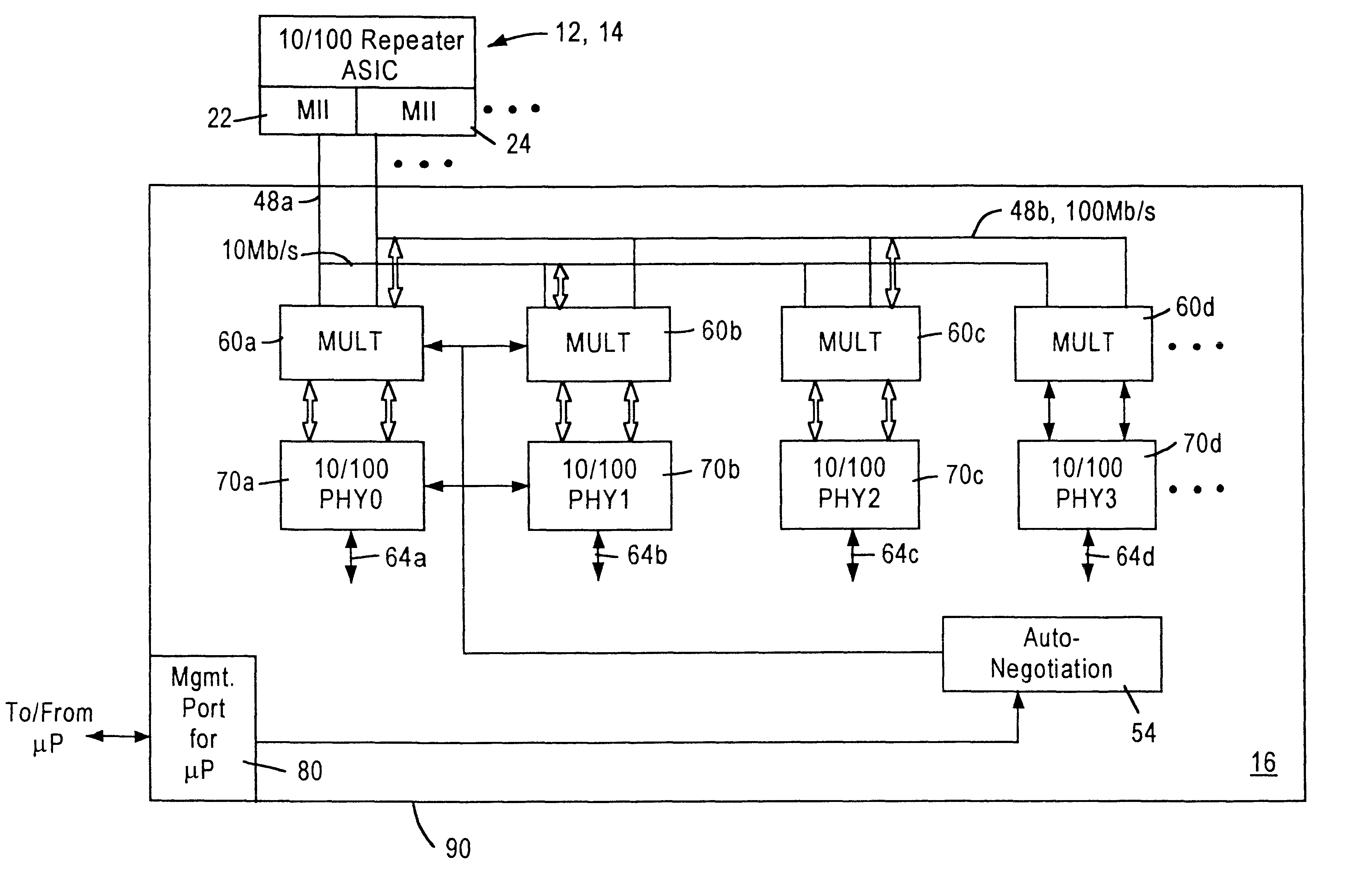
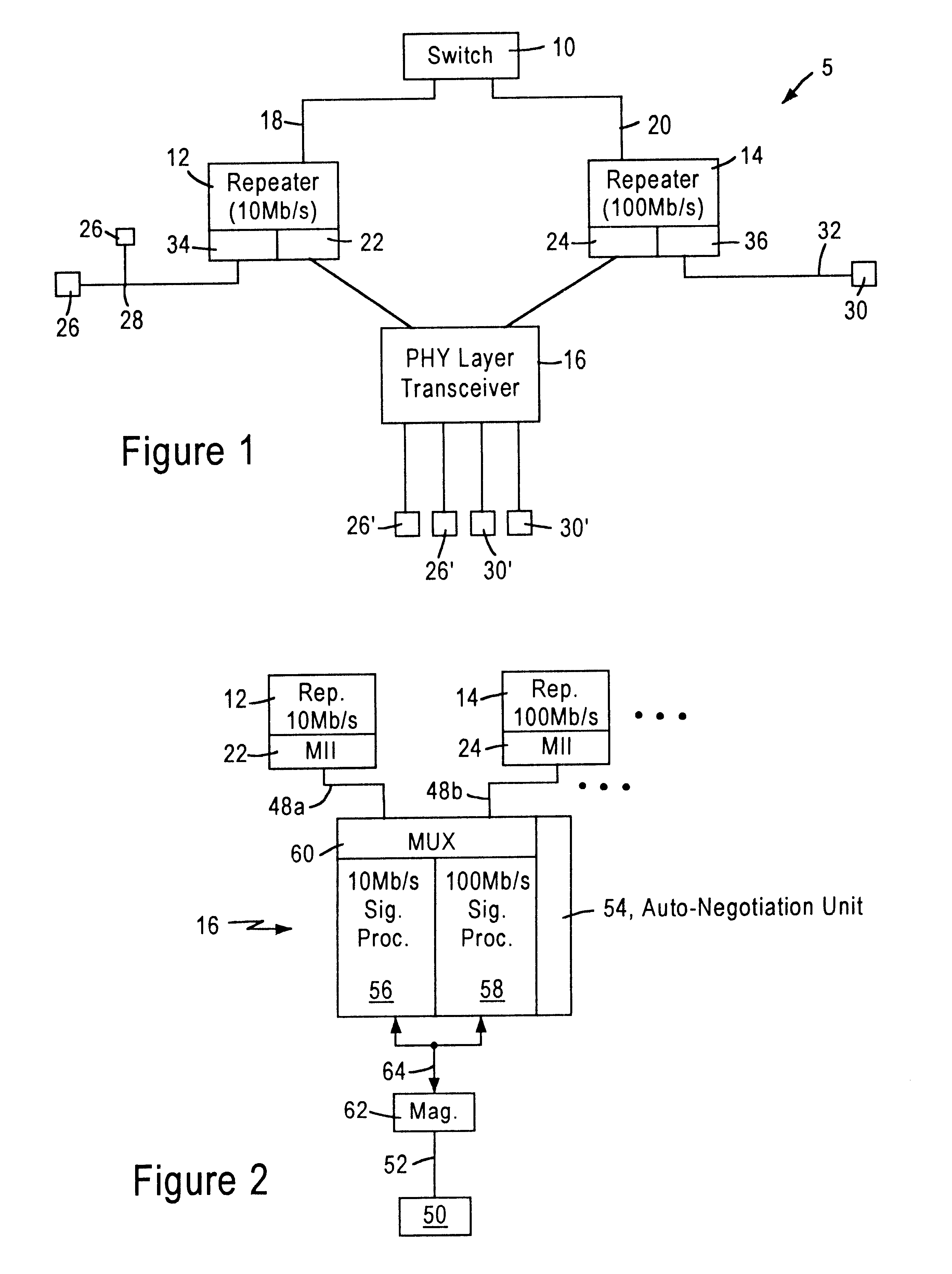
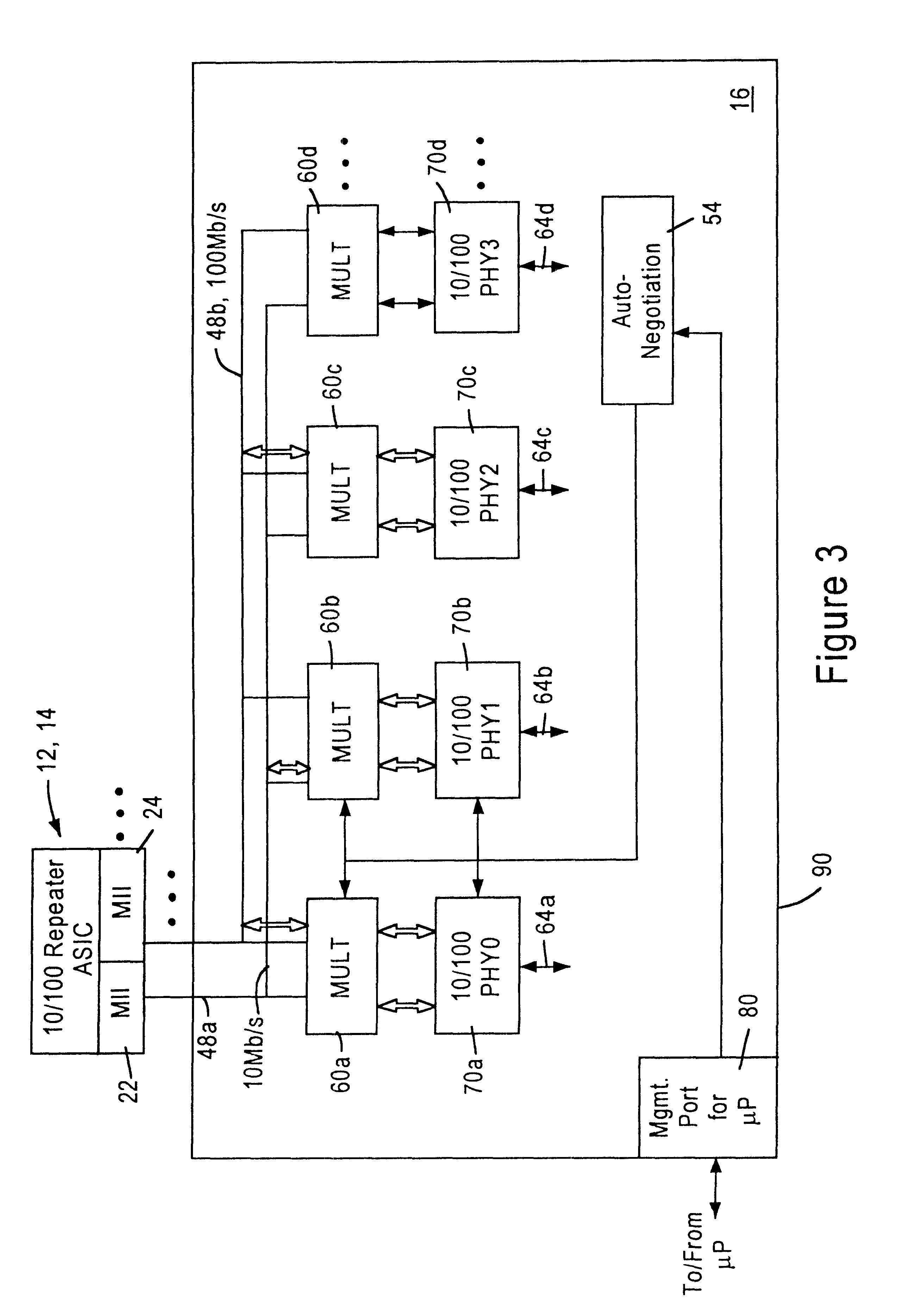
FIG. 1 is a block diagram of an exemplary local area network architecture including a repeater system for transporting network data at different data rates according to an embodiment of the present invention. As shown in FIG. 1, the network 5 includes a network switch 10, a repeater 12 operating at a first data rate such as 10 Mb / s, a second repeater 14 operating at a second data rate such as 100 Mb / s, and a multiple port physical layer transceiver 16. The switch 10 and the repeater 12 transfer network data via a data link 18 operating at the first data rate of 10 Mb / s. The switch 10 and the repeater 14 transfer data via a different data link 20 operating at the second data rate of 100 Mb / s. The repeaters 12 and 14 transfer data to and from the network transceiver 16 via repeater interfaces 22 and 24 operating at 10 Mb / s and 100 Mb / s, respectively. As recognized in the art, the repeater 12 may also transfer network data to individual network workstations 26 operating at 10 Mb / s via ...


PUM


Abstract

A novel method of operating repeaters or other hub devices in a local area network, such as one conforming to Ethernet protocol, in which there are a plurality of repeater interfaces of respectively different data rates for communicating with a link partner on a network medium. The methodology comprises determining the data rate of operation of the link partner, and based on that data rate, automatically steering data between the network medium and a selected one of the repeaters. In a preferred embodiment, a network transceiver comprises one or more physical layer devices (PHY), and a plurality of shared data busses corresponding, respectively, to the speeds of operation of the repeaters, for interconnecting the repeaters and one or more of the physical layer devices. A multiplexer interconnects each of the one or more physical layer devices to a selected one of the plurality of busses, and an auto-negotiation unit controls the multiplexer to interconnect the physical layer devices to corresponding busses selected depending on the operating speed of the link partner.

Description

The present invention relates to network interfacing, and more particularly to a novel network transceiver that steers network data streams to a selected data path compatible with the operating speed of a network link partner.A Local Area Network, or (LAN), is a communications systems that provides a connection among a number of independent computing stations within a small area, such as a single building or group of adjacent buildings. One type of network structure uses one or more repeaters in a star topology, with each repeater having several ports. A data packet received at one port is retransmitted to all other ports of the repeater. Each repeater in turn restores timing and amplitude degradation of data packets received at one port and retransmits the packets to all other ports.Traditional Ethernet networks (10BASE-T) operate at 10 Mb / s Ethernet protocol, as described by IEEE Standard 802.3; the majority of Ethernet interfaces currently operate at this data rate. However, a ne...

Claims


Application Information

Patent Timeline
Patent Type & Authority Patents(United States)
IPC IPC(8): G01B7/02H04L29/08H04J3/06H04L12/46H04B3/46H04L29/06H04L12/413H04L12/24H04L12/407G01R31/08H04L25/03
CPCG01B7/02H04B3/46H04J3/0688H04L69/323H04L25/03885H04L41/046H04L69/18H04L12/4625G01R31/086H04L12/40136H04L49/3054
Inventor MCROBERT, STEPHENCRAYFORD, IAN S.
Owner GLOBALFOUNDRIES INC
Why Eureka
Try Eureka