Fuel tank equipped with a gas evacuating system

a technology of evacuating system and fuel tank, which is applied in the direction of container, understructure, item transportation vehicle, etc., can solve the problems of cost and reliability, tank pressure can be subjected to dangerous rises in pressure, and the structure of known devices is complex

Inactive Publication Date: 2003-05-06
CO PLASTIC OMNIUM
View PDF8 Cites 36 Cited by
  • Summary
  • Abstract
  • Description
  • Claims
  • Application Information

AI Technical Summary

Benefits of technology

The membrane of the invention has the advantage that in addition to performing the SLV function, it replaces the ROV dev

Problems solved by technology

It is also known that the motion of a vehicle subjects its fuel tank to shaking that causes fuel vapor to appear over the liquid fuel, which fuel vapor must be evacuated since otherwise the tank can be subjected to dangerous rises in pressure.
As a result, t

Method used


Image

  • Fuel tank equipped with a gas evacuating system
  • Fuel tank equipped with a gas evacuating system
  • Fuel tank equipped with a gas evacuating system

Examples


Embodiment Construction

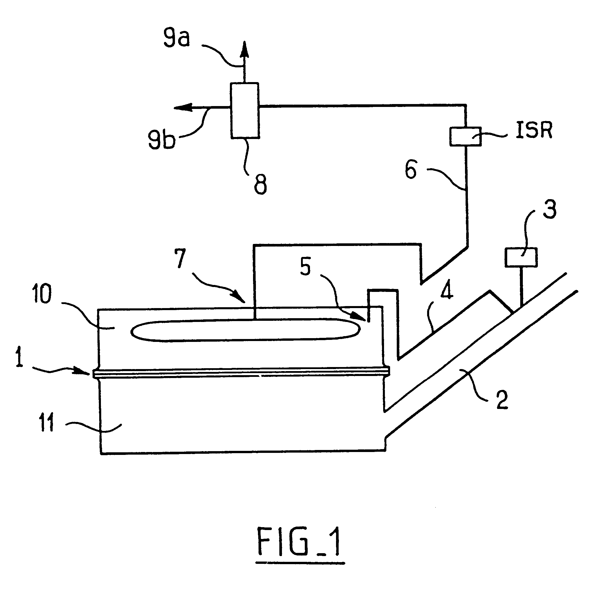
FIG. 1 shows diagrammatically a fuel tank 1 for a motor vehicle, the tank including a tube 2 for filling purposes.

The tube 2 is provided with a safety valve 3 that opens in the event of negative or positive pressure inside the tank exceeding predetermined values, and it is connected by a branch duct 4 to a point 5 of the tank 1.

Opening of the valve 3 is exceptional, and normally the tank is ventilated by means of a circuit 6 that is connected to the atmosphere and also to a high point of the tank 1.

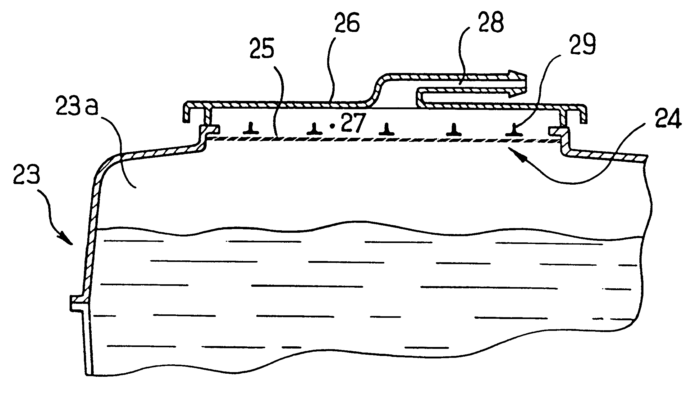
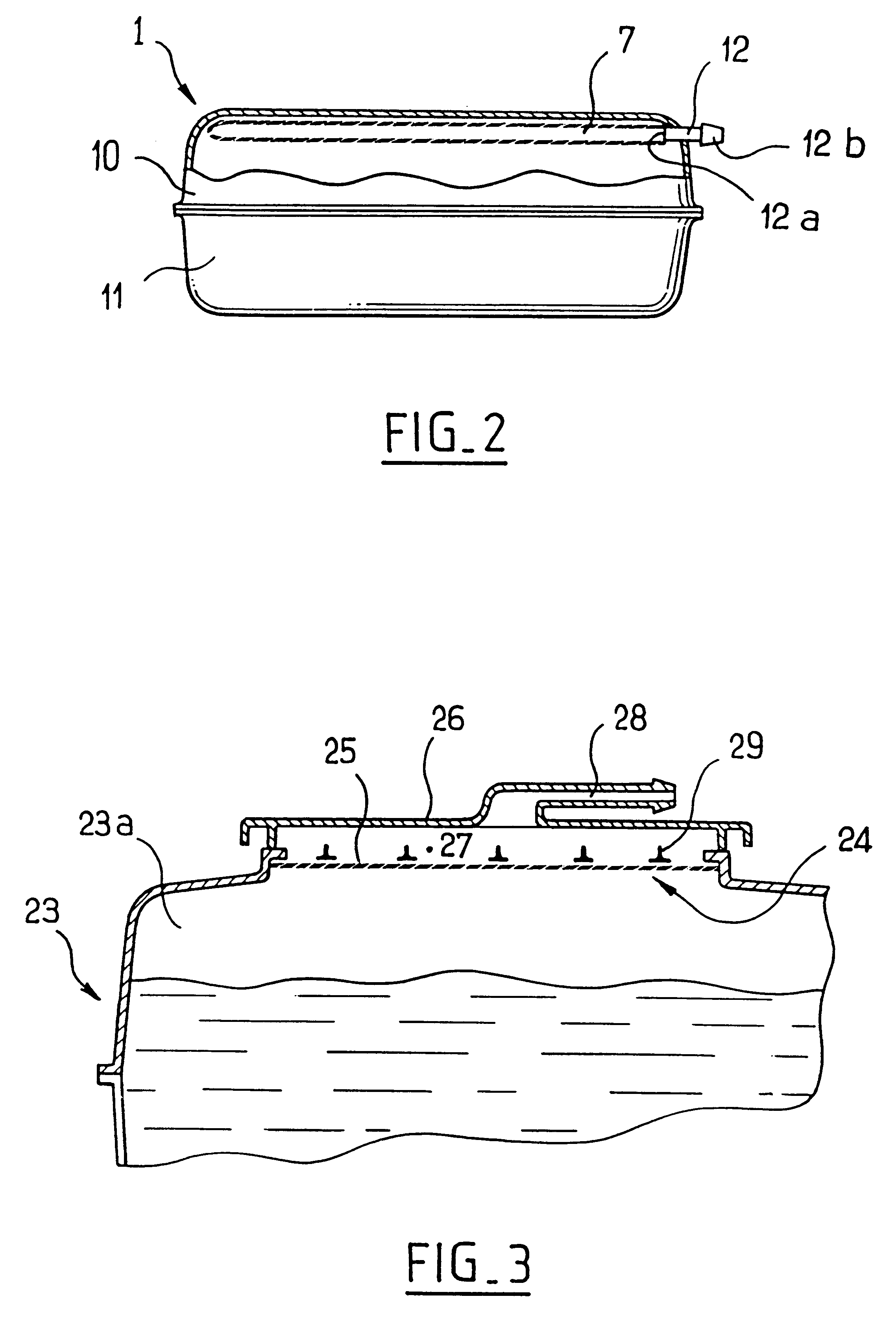
A membrane 7 that is permeable to air and to fuel vapor, but that is impermeable to liquid fuel, is placed in said circuit 6 inside the vessel constituting the tank, so as to prevent liquid fuel leaving the tank, whatever the position of the tank.

The major portion of the membrane 7 extends across a horizontal section of the tank.

The membrane 7 thus performs two functions, one of separating liquid fuel from vapor, known as the "SLV" function, and the other of providing safety in the event ...


PUM


Abstract

The invention relates to a fuel tank comprising a vessel for containing fuel and a system for evacuating the gases contained in the vessel. The system has a passage putting the inside of the vessel into communication with the outside of the vessel, and the passage is closed by a membrane suitable for allowing air and fuel vapor to pass therethrough while preventing liquid fuel from passing therethrough. The membrane is situated inside the vessel and it extends over the major portion of the top wall of the vessel.

Description

The present invention relates to a fuel tank comprising an vessel for containing fuel and a gas evacuation system.In order to fill a fuel tank without causing fuel to back up in the filler tube, it is known that the gas contained in the tank must be allowed to escape as the level of liquid in the tank rises.It is also known that the motion of a vehicle subjects its fuel tank to shaking that causes fuel vapor to appear over the liquid fuel, which fuel vapor must be evacuated since otherwise the tank can be subjected to dangerous rises in pressure.However, it will be understood that evacuating fuel vapor in this way must take place without any liquid fuel being able to escape from the tank together with the vapor.To this end, it is known to provide a tank with one or more gas evacuation ducts connected to respective devices (which are generally check valves) having various functions including the function of allowing gases to pass while preventing liquid fuel from passing. This is ref...

Claims


Application Information

Patent Timeline
IPC IPC(8): B60K15/035B60K15/03
CPCB60K15/035B60K15/03177B60K2015/03453B60K15/03504
Inventor ARNAL, ANDREDECOBERT, PHILIPPEROSSEEL, ALEXIS
Owner CO PLASTIC OMNIUM
Why Eureka
Try Eureka