Drainage catheter

a technology of draining catheter and catheter body, which is applied in the direction of wound draining, dilating device, surgery, etc., can solve the problems of inadvisable patient removal, difficult catheter inserting size, and inconvenient patient removal

Inactive Publication Date: 2003-05-06
APPL MEDICAL RESOURCES CORP
View PDF16 Cites 76 Cited by
  • Summary
  • Abstract
  • Description
  • Claims
  • Application Information

AI Technical Summary

Problems solved by technology

There are several disadvantages associated with this catheter and its method of use.
Significant among these disadvantages is the construction of the Foley catheter, which typically is manufactured by dip-molding a solid mandrel.
This size of catheter is difficult to insert and very uncomfortable for the patient.
Patient frustration sometimes leads to inadvisable patient removal, even with the balloon inflated.
This of course can be very damaging and traumatic to the patient.
The hard rubber tip of a Foley catheter is also thought to contribute significantly to patient discomfort.
The resulting irritation also contributes to patient frustration.
Further discomfort results from the fact that the walls of the catheter must be relatively thick and somewhat rigid in order to resist kinking.
In order to subtract as little space as possible from this primary lumen, inflation lumens have tended to be relatively small and consequently more suscepti

Method used


Image

  • Drainage catheter
  • Drainage catheter
  • Drainage catheter

Examples


Embodiment Construction

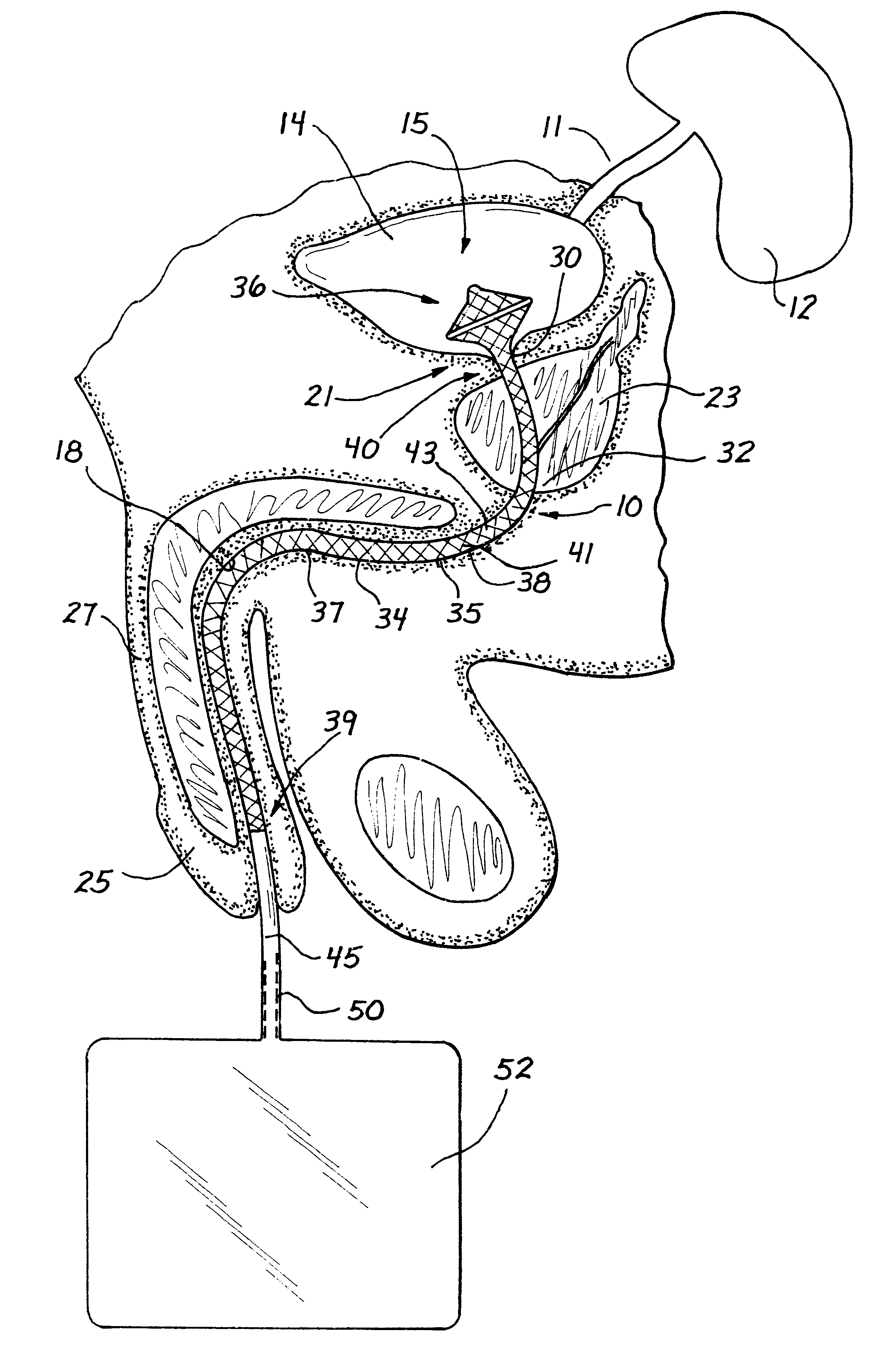
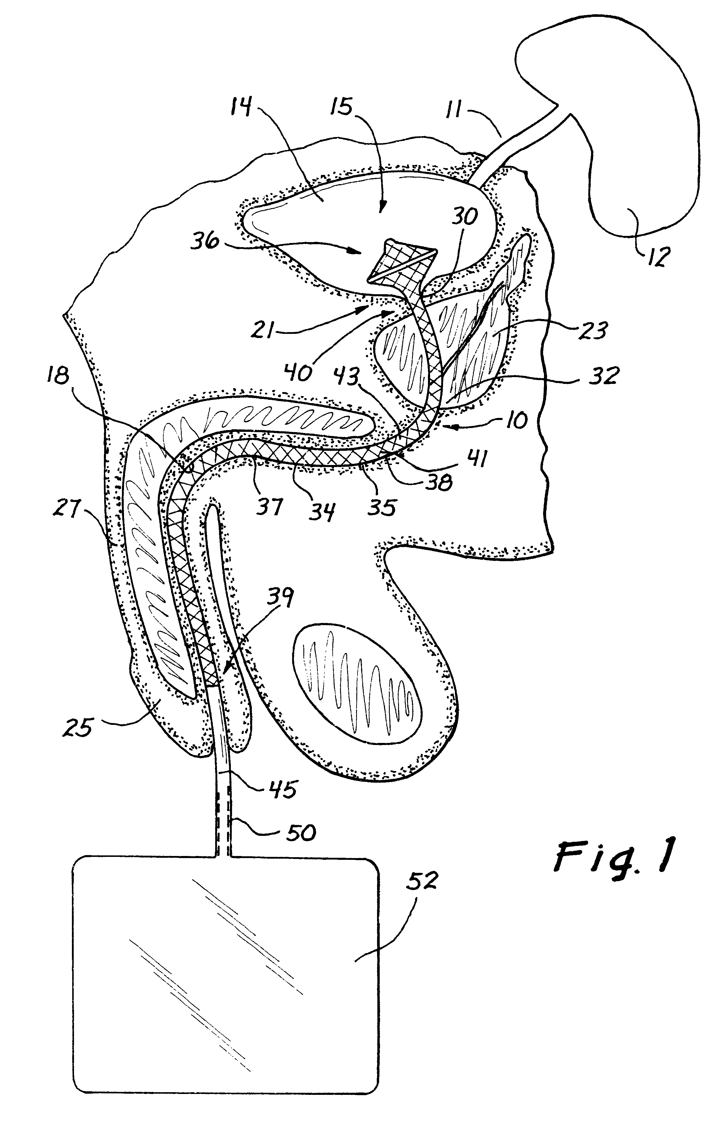
A drainage catheter specifically adapted for use in the urinary tract of a patient is illustrated in FIG. 1 and designated by the reference numeral 10. In this view, the urinary tract includes a ureter 11 extending in fluid communication between a kidney 12 and a bladder 14 having a bladder cavity 15.

A urethra 18 begins at a bladder neck 21 and passes outwardly through a prostrate 23 and a meatus 25 of a penis 27. Sphincters 30 and 32 are disposed at opposite ends of the prostate 23. These sphincters include a secondary sphincter 30 disposed between the prostate 23 and the bladder neck 21, and a primary sphincter 32 disposed at the outward end of the prostate 23. Under normal conditions, the urethra 18 drains urine from the bladder 14 under the control of the sphincters 30 and 32, which open and close the urethra 18.

When the urethra 18 is compromised or otherwise blocked, urine cannot naturally drain from the bladder 14, even when the sphincters 30 and 32 are open. Under these condi...


PUM


Abstract

A drainage catheter is adapted to drain fluid from the body cavity through a body conduit and includes an elongate tube having a distal end and a retention member disposed at the distal end and adapted for movement between the low-profile state facilitating insertion of the catheter and a high-profile state facilitating the tension of the catheter in its operative position. A woven mesh forms at least a portion of one of the tube and the retention member, and can be made permeable or impermeable in various regions of the catheter. The woven mesh can be formed of filaments heat-settable so that the catheter automatically moves to the high-profile state. Insertion of the catheter can be facilitated using an obturator and a guidewire in an associated method, an obturator facilitating insertion of the catheter can be removed to permit the catheter to automatically return to a normal, high-profile state.

Description

1. Field of the InventionThis invention relates generally to drainage catheters adapted for use in draining a fluid from a body cavity and through a body conduit. Typical of such devices are urinary catheters that are adapted to drain urine from a bladder and through a urethra of a patient.2. Discussion of the Prior ArtUrinary drainage catheters are used to provide an outlet for the urinary bladder when the normal outlet lumen (the urethra) is compromised or obstructed. Such catheters have been used on a more permanent basis, when the patient is incapable of controlling a capable urinary system due to sedation or lack of mental capacity. A typical urinary catheter is the Foley catheter, which is frequently used for bladder drainage. The Foley catheter is a thick-walled rubber tube with an inflatable balloon near its distal end. The catheter is inserted with the balloon deflated, through the urethra (which extends through the prostate and a bladder neck), and into the bladder cavity....

Claims


Application Information

Patent Timeline
IPC IPC(8): A61M25/04A61M25/02A61M27/00A61M25/00
CPCA61M25/04A61M25/0017
Inventor HART, CHARLES C.CLAYMAN, RALPH V.HILAL, SAIDHILAL, NABILBRUSTAD, JOHNPRAVONGVIENGKHAM, BOUNSAVANHDULAK, GARY R.
Owner APPL MEDICAL RESOURCES CORP
Why Eureka
Try Eureka