Linear guide apparatus

a guide apparatus and linear technology, applied in the direction of track-braking member co-operation, manufacturing tools, gearing, etc., can solve the problems of reducing the response characteristic of the brake member when it is pressed, degrading the positioning accuracy of the slider, and difficult to control the frictional force with high accuracy

Inactive Publication Date: 2003-05-13
NSK LTD
View PDF11 Cites 70 Cited by
  • Summary
  • Abstract
  • Description
  • Claims
  • Application Information

AI Technical Summary

Benefits of technology

In the thus structured linear guide apparatus, since the brake member is contacted with the other portions of the side surface of the guide member than the guide surface thereof, not only the slider can be prevented from being pushed up but also the guide surface can be prevented against wear. Thanks to this, the positioning accuracy of the slider can be kept at a high level.
Also, the drive device, which is used to drive the brake member, includes an advance and retreat member which can be moved in the direction to be contacted with and separated from the side surface of the guide member. And, the drive device is structured such that it can drive the advance and retreat member in the direction to approach the side surface of the guide member to thereby press the brake member against the side surface of the guide member and also can drive the advance and retreat member in the direction to part away from the side surface of the guide member to thereby remove the pressure thereof. Also, the brake member is supported with high rigidity in other directions thereof than the direction to be contacted with and separated from the side surface of the guide member. Thanks to this, the brake member can be operated with no delay with respect to the operation of the advance and retreat member, that is, can be operated quickly with a good response characteristic with respect to the operation of the advance and retreat member, thereby being able to control the frictional force of the brake member with high accuracy.

Problems solved by technology

However, because the brake member is pressed against the rolling body rolling groove 58 to thereby a frictional force, there is a tendency that the rolling body rolling groove 58 is worn to such a degree that cannot be ignored, which results in the degraded positioning accuracy of the slider 54 and table 52.
However, in case where the elastic force of the coiled spring is set large, there increases the load that is produced when the brake member is pressed by the oil cylinder against the elastic force of the coiled spring, which degrades the response characteristic of the brake member when it is pressed.
This invites the delayed generation of the frictional force, which makes it difficult to control the frictional force with high accuracy.

Method used


Image

  • Linear guide apparatus
  • Linear guide apparatus
  • Linear guide apparatus

Examples


second embodiment

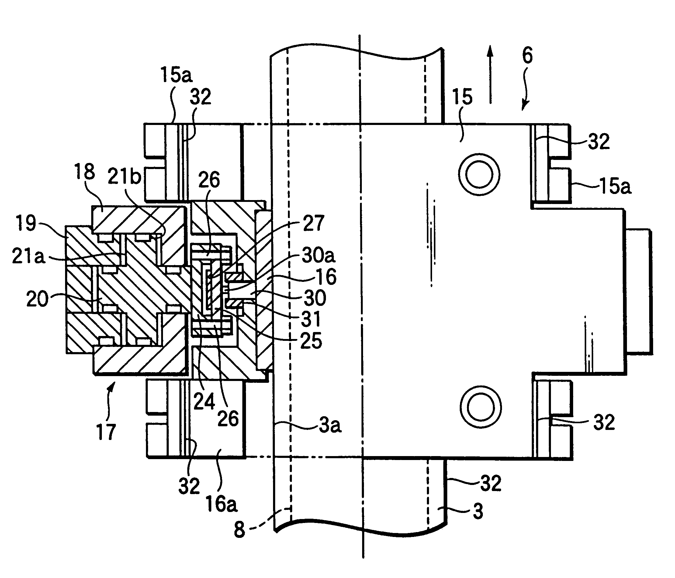
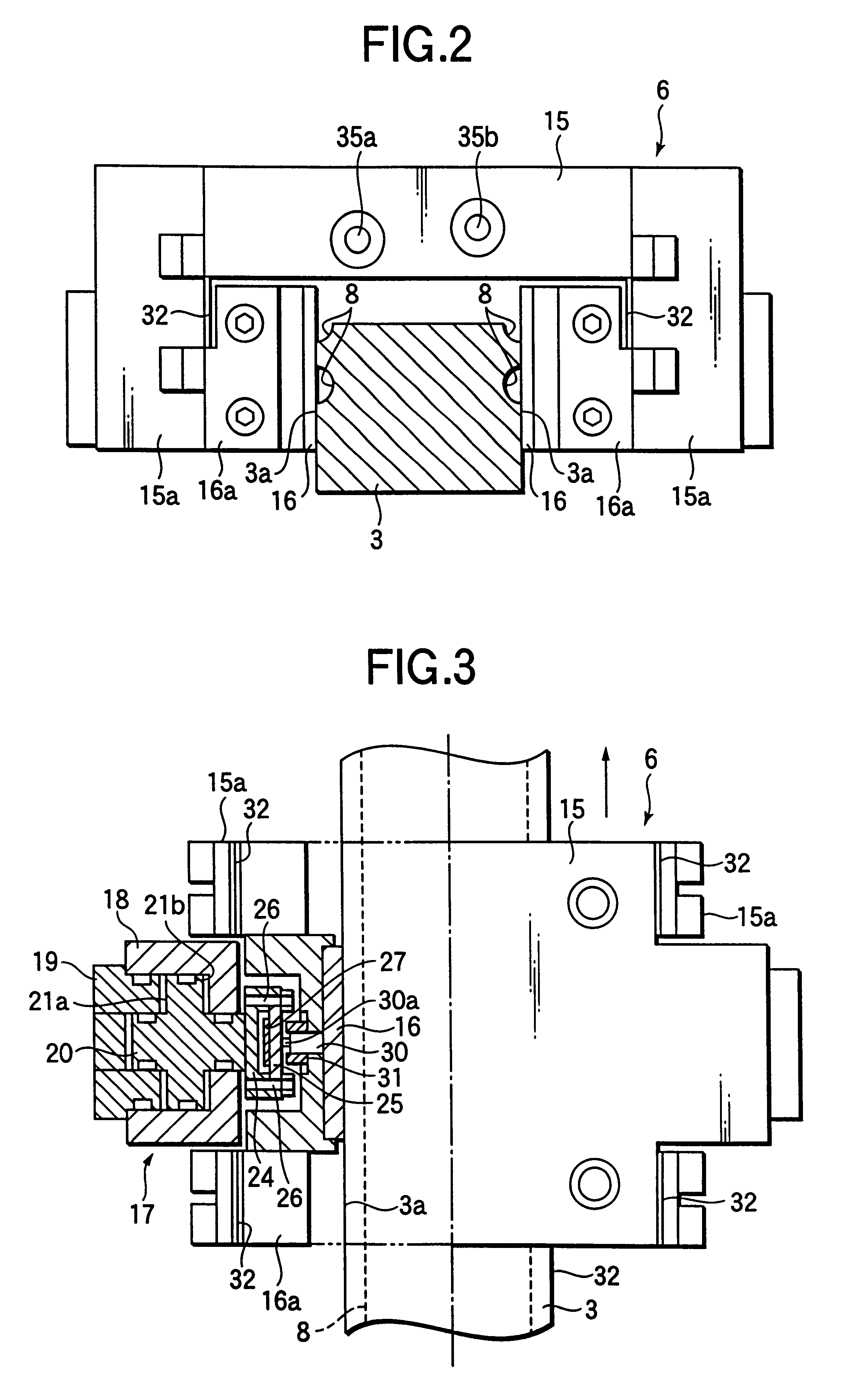
Referring in more detail to the structure of the second embodiment, in the middle portion of a beam 25 disposed in a pressure detect portion formed in the piston member 20, there is disposed a support piece 25b through a hinge portion 25a integrally with the beam 25, while the brake member 16 and holder 16a are respectively mounted on the support piece 25b through bolts 37. Due to provision of such hinge structure, even in case where there exist dimensional errors and / or mounting errors in the brake member 16 and holder 16a, when the piston member 20 is moved toward the side surface 3a of the guide rail 3 and is then contacted with the side surface 3a, the hinge portion 25a is elastically deformed to thereby absorb such dimensional errors and / or mounting errors, so that the whole of the brake member 16 can be pressure contacted with the side surface 3a of the guide rail 3 substantially uniformly.

In the case of the second embodiment, since the brake member 16 and holder 16a are struc...

first embodiment

Further, in the present linear guide apparatus 1, similarly to the first embodiment, because the brake member 16 is contacted with other portions of the side surface 3a of the guide rail 3 than the rolling body rolling groove 8 thereof, not only the slider 4 is prevented from being pushed up but also the rolling body rolling groove 8 is prevented against wear. This makes it possible to keep the positioning accuracy of the slider 4 and table 2 at a high level.

By the way, the invention is not limited to a linear guide apparatus of a rolling guide type in which a large number of rolling bodies are interposed between a guide member and a slider, but can also apply to a linear guide apparatus of a sliding type.

As has been described heretofore, according to the invention, since a brake member is contacted with other portions of the side surface of a guide member than the guide surface thereof to thereby produce a frictional force between them, not only a slider can be prevented from being...


PUM

PropertyMeasurementUnit
pressureaaaaaaaaaa
rigidityaaaaaaaaaa
speedaaaaaaaaaa

Abstract

The linear guide apparatus includes a guide rail 3 including a rolling body rolling groove 8 and a friction apply unit 6 assembled to the guide rail 3. The friction apply unit 6 includes a unit main body 15, a brake member 16, an oil pressure cylinder 17 and a plate spring 32. The brake member 16 is disposed so as to face the side surface 3a of the guide rail 3 and can be contacted with the other portions of the side surface 3a than the rolling body rolling groove 8 thereof. The oil pressure cylinder 17 includes a piston member 20 which is structured to be driven in a positive direction to thereby press the brake member 16 against the side surface 3a of the guide rail 3 and also the piston member 20 can be driven in the opposite direction to thereby remove the pressure of the brake member 16 from the side surface 3a.

Description

1. Field of the InventionThe present invention relates to a linear guide apparatus which is used in a machine tool and an industrial machine.2. Description of the Related ArtTo guide a table of a machine tool or an industrial machine which can be moved at a relatively high speed by a ball screw or a linear motor, there is used such a linear guide apparatus 51 as shown in FIG. 8.The linear guide apparatus 51 shown in FIG. 8, which is generally called a linear guide, comprises guide rails 53 serving as guide members respectively extending in one direction, and sliders 54 movably assembled to their associated guide rails 53. In the outer surface of each guide rail 53, there is formed a rolling body rolling groove 58 which serves as a guide surface; in each slider 54, there is formed a load rolling body rolling groove serving as a load guide surface in such a manner that it faces the rolling body rolling groove 58 of the guide rail 53; between the rolling body rolling groove 58 and load...

Claims


Application Information

Patent Timeline
Patent Type & Authority Patents(United States)
IPC IPC(8): B23Q1/58B23Q1/26B23Q1/28B23Q1/25F16D65/14F16C29/06F16D63/00F16D66/00F16H25/24F16C29/00F16C29/10F16C29/12F16H25/20
CPCB23Q1/28B23Q1/58F16C29/00F16C29/008F16C29/06F16C29/10F16D63/008F16C29/12Y10T74/18704F16D2066/005F16D2121/02F16H25/2454Y10T74/18648F16C2322/39
Inventor AKIYAMA, MASARUKATO, SOICHIRONAKAMURA, SHINYAYABE, SHIROJI
Owner NSK LTD
Why Eureka
Try Eureka