Power floating production and ship propulsion supported by gyroscope and energized by seas

a technology of gyroscope and power floating, which is applied in the direction of marine propulsion, vessel construction, transportation and packaging, etc., can solve the problems of increasing the rim and not expanding the fortune in tim

Inactive Publication Date: 2003-05-13
GORSHKOV VLADISLAV VASILYEVICH
View PDF19 Cites 89 Cited by
  • Summary
  • Abstract
  • Description
  • Claims
  • Application Information

AI Technical Summary

Problems solved by technology

The gyro fulcrum hinders free ship rocking through the loaded converter and causes trim increasing.
But the fortune is not expanding in time.

Method used


Image

  • Power floating production and ship propulsion supported by gyroscope and energized by seas
  • Power floating production and ship propulsion supported by gyroscope and energized by seas
  • Power floating production and ship propulsion supported by gyroscope and energized by seas

Examples


Embodiment Construction

1. Developing the Mechanical Structures Converting the Ship Rocking to Customary Power.

1.1. Physical basis.

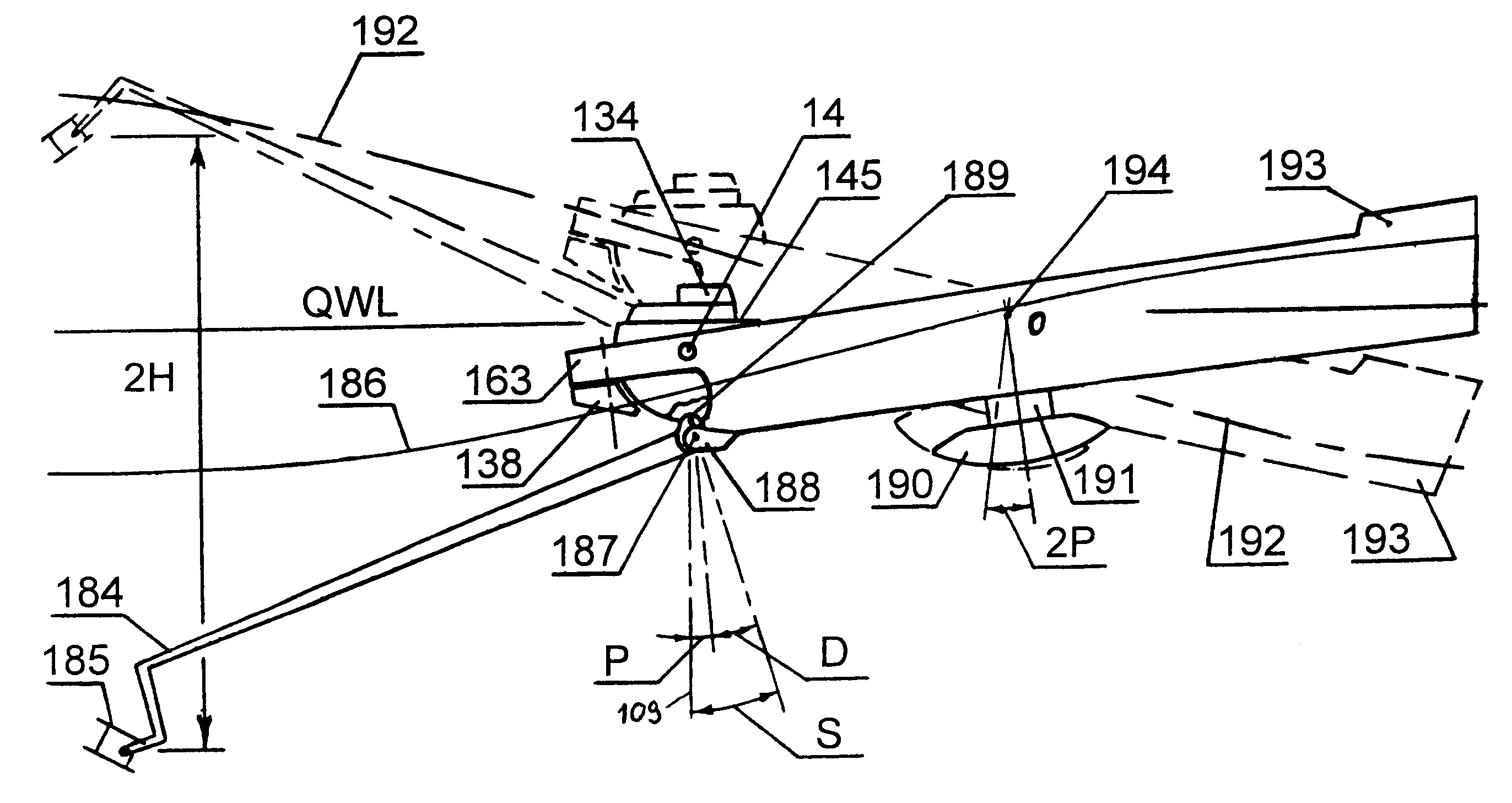
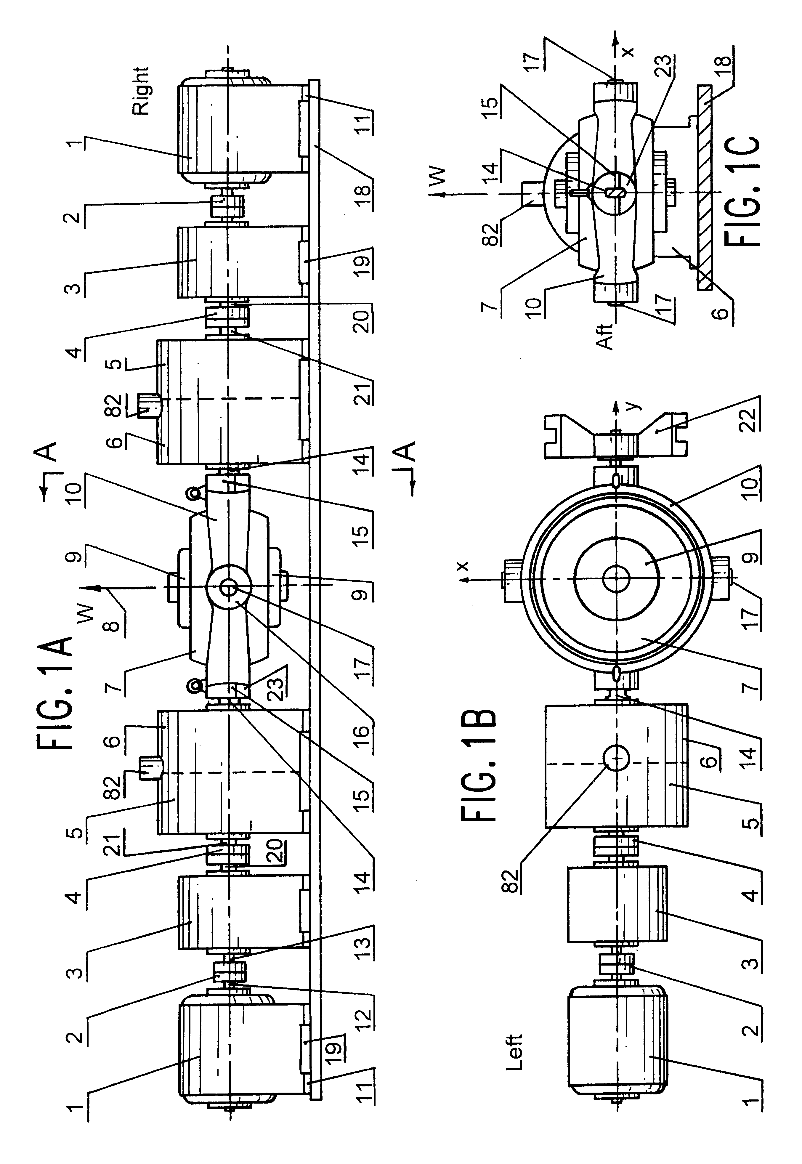
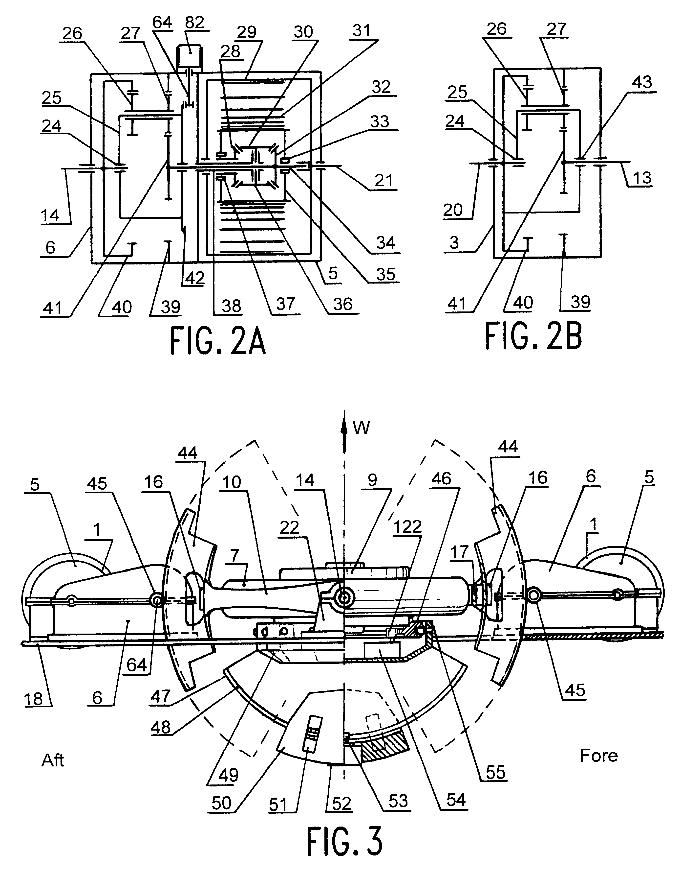
Each flank of the GRP-plant (FIG. 1a,c) consists of the generator 1, the step up gearbox 3, the converter `angle oscillations to shaft revolution` 5-6. Its right flank (if presented) is the mirror reflection of the left flank with components indexed by `a`. Between these there is the gyroscope 7. The GRP-station is mounted on base plate 18 transmitting pitch motion to all components except the gyroscope 7. The gyroscope 7 is mounted with its external frame 10 on the flattened shaft ends 14, 14a of the converters 6 and 6a. We explain working process using the left flank.

When the ship is rocking the converter 6 its input shaft 14 is kept immobile by the still frame 10 of the gyroscope 7 with the flattened end. Thus the shaft 14 and the converter case 6 oscillate relatively each other. The converter 5-6 transforms oscillations of the input shaft 14 to one way revolutions of the ou...


PUM


Abstract

To access the inexhaustible energy source like seas and oceans we need to learn how to convert its wave motion to the customized power for our ships, for our existing littoral settlements and our future ocean settlements. Here is an attempt to develop method of the conversion the wave energy to power with floating means based on a gyroscope strong capability to resist against the outer force moment trying to tilt it to any side.The gyroscope is used as the fulcrum torque dynamic supporting instead traditional static base used in the issued devices. Alternate force moment created by the waves and transmitted to the gyroscope (via the floating body and the wave energy converter) inducts alternative gyro precession so as the gyroscope axis hesitates about mean position. This is important because it allows the gyroscope to keep dynamic fulcrum torque in unlimited time.The few gyroscope precession control devices and methods have been developed to compensate other reasons enforcing the mean gyro axis to drift from initial plumb.Also here are developed the new ship architecture with the separated floating gyro section. The wagging propulsor driven by the pitching and with strokes amplified by the fulcrum gyro section, the spring moment generator for the gyroscope drift compensation, non gyroscope floating power station able to derive, convert, accumulate and transmit wave energy to consumer also have been developed here.

Description

STATEMENT REGARDING FEDERAL SPONSORED R & DThe invention has been created by the author self with his own means in duty free time.REFERENCE TO A MICROFICHE APPENDIXNot applicable.Endeavor: Any rocking process carries energy. Seas produce the most powerful natural rocking. It should be used for powering of ships, bouts, others floating means and also to energize floating power plants. Here is given the method based on gyroscope capability to keep stable its angle attitude in space providing power extraction from rocking processes produced by seas. As positive results the method allows to:furnish any rocking floating mean (a ship, a raft, a boat, . . . ) by the gyroscope supported rocking energized power (GRP-)plant producing electric or / and hydra-pneumatic power;propel a ship with rocking energy transmitted to a propeller or wagging propulsor directly or through electromechanical and / or hydraulic converters;build seas floating power plants for power supply seashore settlements or mas...

Claims


Application Information

Patent Timeline
Patent Type & Authority Patents(United States)
IPC IPC(8): B63H19/00B63H19/02
CPCB63H19/02Y02T70/59Y02T70/5236
Inventor GORSHKOV, VLADISLAV VASILYEVICH
Owner GORSHKOV VLADISLAV VASILYEVICH
Why Eureka
Try Eureka