Variable compression ratio pistons and connecting rods

a compression ratio and piston technology, applied in the direction of engines, mechanical equipment, machines/engines, etc., can solve the problems of engine knocking in a motor vehicle typically prevailing, gasoline engine whose compression ratio remains invariant as operating conditions change, and engine is incapable of achieving more efficient operation

Inactive Publication Date: 2003-05-27
FORD GLOBAL TECH LLC
View PDF13 Cites 32 Cited by
  • Summary
  • Abstract
  • Description
  • Claims
  • Application Information

AI Technical Summary

Problems solved by technology

A gasoline engine whose compression ratio remains invariant as operating conditions change is said to be knock-limited.
However, those conditions that give rise to engine knocking in a motor vehicle typically prevail for only limited times as the vehicle is being driven.
At other times, the engine could operate with better efficiency, and still without knocking, if the compression ratio could be made higher, but unfortunately the engine is incapable of achieving more efficient operation during those times because its compression ratio cannot change.

Method used


Image

  • Variable compression ratio pistons and connecting rods
  • Variable compression ratio pistons and connecting rods
  • Variable compression ratio pistons and connecting rods

Examples


embodiment 20

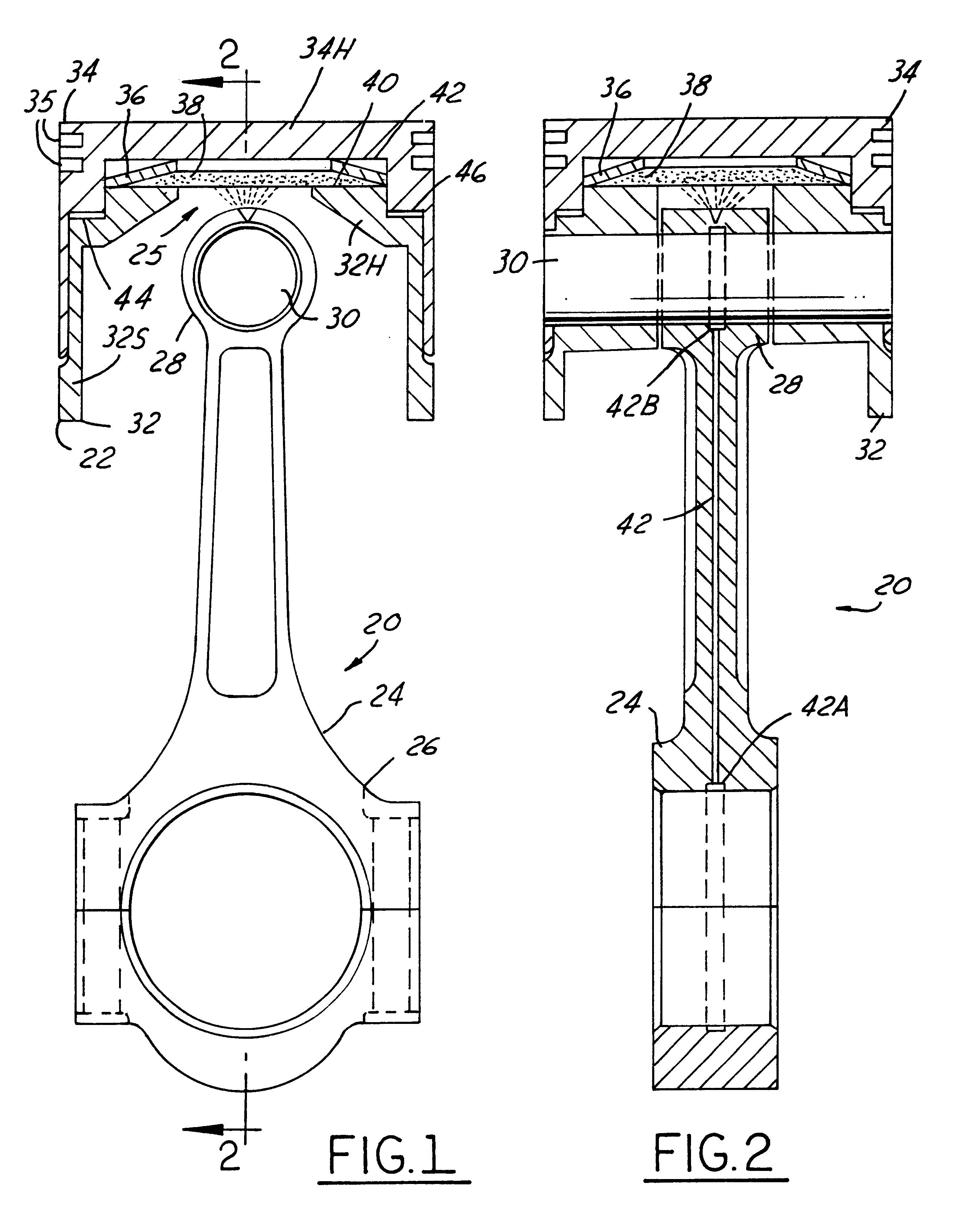
FIGS. 1 and 2 disclose a first piston / connecting rod embodiment 20, comprising a piston 22 and a connecting rod 24, for endowing an engine with a variable compression ratio by embodying a variable length mechanism 25 in piston 22.

Connecting rod 24 comprises a large end 26 for journaling on a crank pin of a crankshaft (not shown) and a small end 28 for journaling on a central portion of a wrist pin 30 that couples the connecting rod to piston 22. Connecting rod 24 has a fixed length between the centers of its large and small ends, and it connects piston 22 with the crank pin to relate reciprocal motion of piston 22 to rotary motion of the crankshaft.

Piston 22 comprises a first part 32 and a second part 34. Each part may be considered to have a respective head 32H, 34H, and a respective skirt 32S, 34S. Wrist pin 30 connects the connecting rod small end 28 only to part 32 so that the travel of part 32 within the engine cylinder is exactly equal to the stroke of connecting rod 24. Part ...

embodiment 80

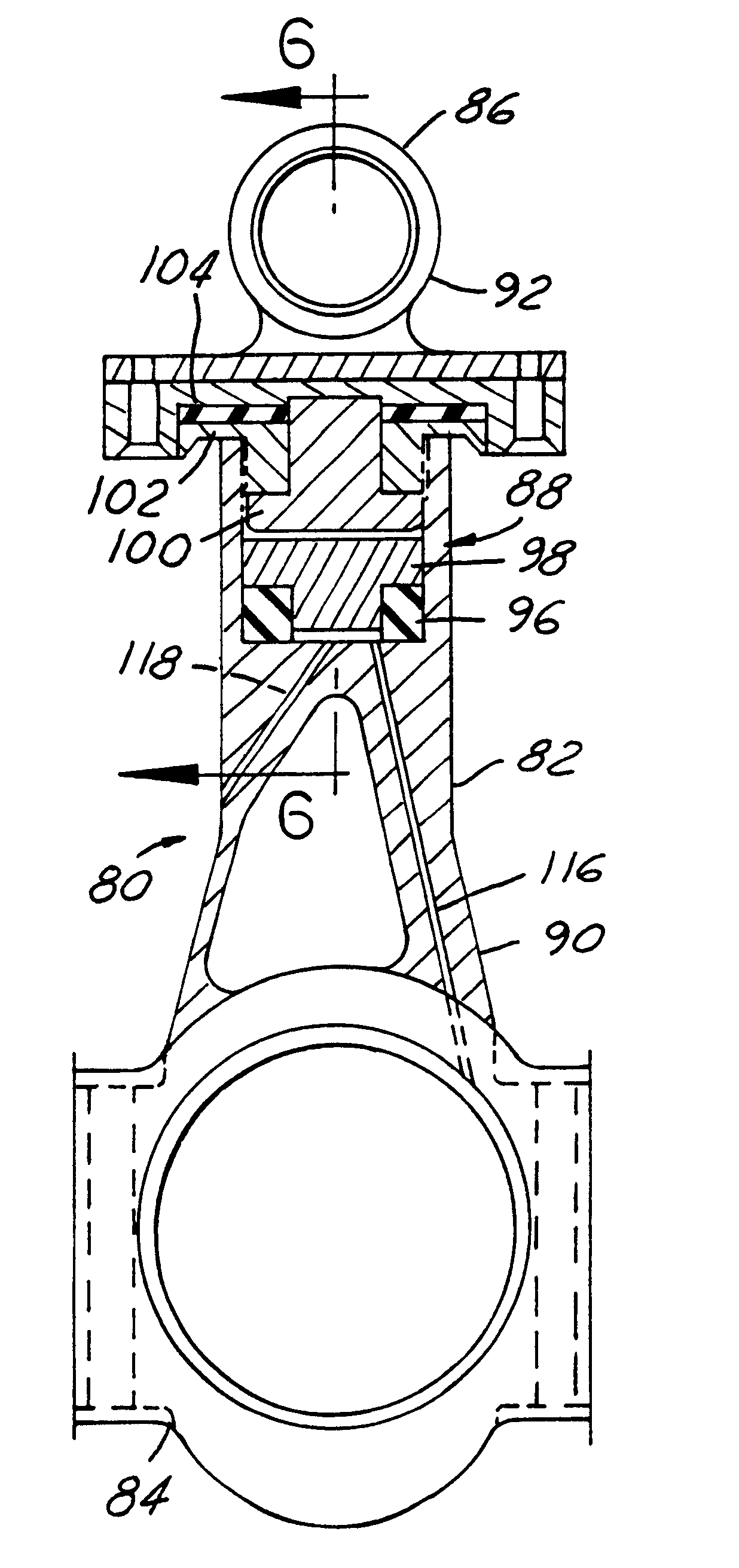
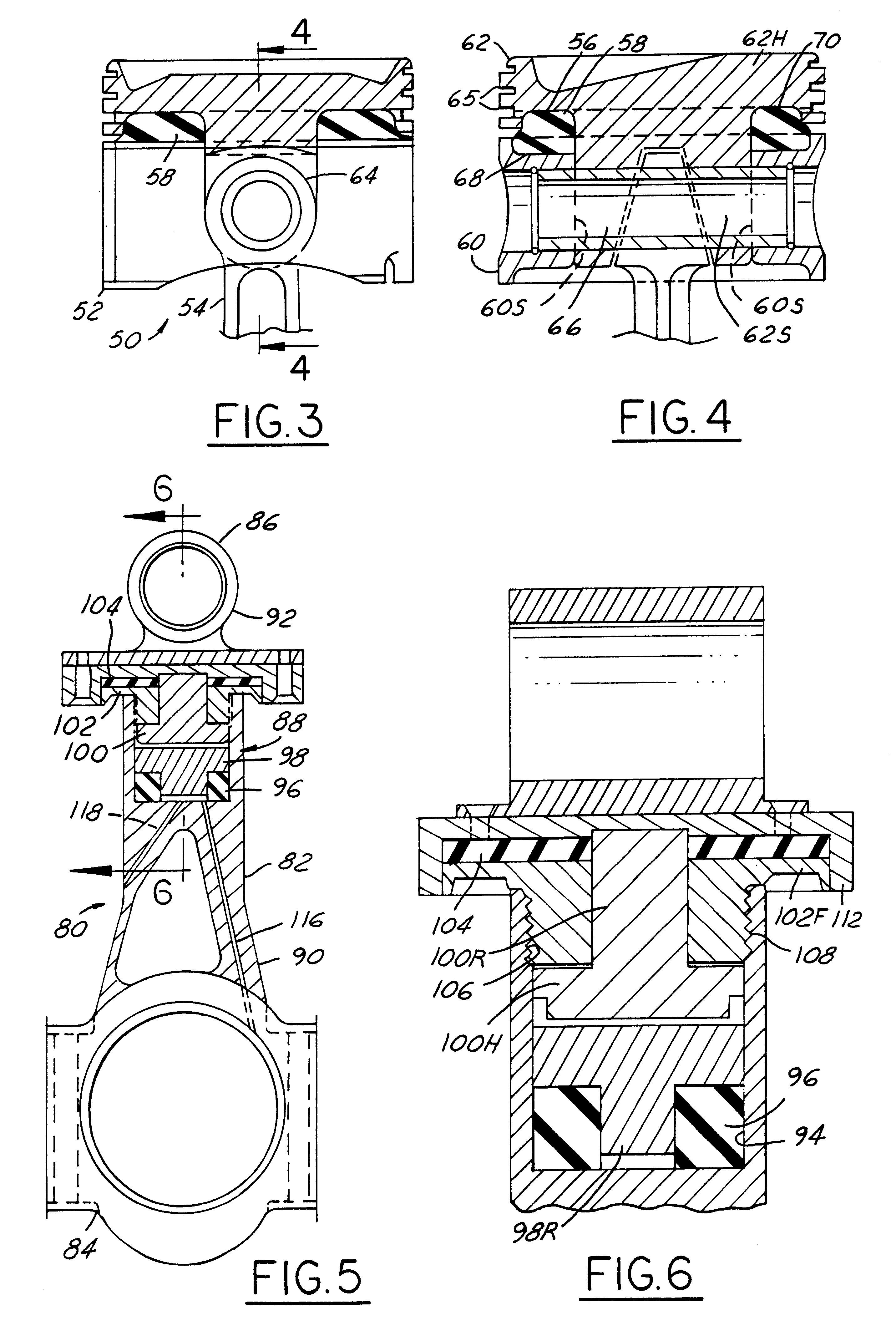
FIGS. 5 and 6 show the connecting rod 82 of a third piston / connecting rod embodiment 80 for endowing an engine with a variable compression ratio. Connecting rod 82 comprises a large end 84 for journaling on a crank pin of a crankshaft (not shown) and a small end 86 for journaling on a central portion of a wrist pin (also not shown) for coupling the connecting rod to the piston (also not shown). A variable length mechanism 88 is embodied in the connecting rod between its large and small ends to provide for variation in overall length between the large and small ends.

Connecting rod 82 comprises a first part 90 containing large end 84 and a second part 92 containing small end 86. The end of part 90 opposite large end 84 comprises a blind hole 94. Mechanism 88 comprises a first elastomeric mass 96, a control plug 98, a control ram 100, a lower retainer 102, and a second elastomeric mass 104.

Elastomeric mass 96 comprises a flat ring of relatively higher modulus of elasticity disposed at ...

embodiment 120

FIGS. 7 and 8 show the connecting rod 122 of a fourth piston / connecting rod embodiment 120 for endowing an engine with a variable compression ratio. Connecting rod 122 comprises a large end 124 for journaling on a crank pin of a crankshaft (not shown) and a small end 126 for journaling on a central portion of a wrist pin (also not shown) for coupling the connecting rod to the piston (also not shown). A variable length mechanism 128 is embodied in the connecting rod between its large and small ends to provide for variation in overall length between the large and small ends.

Connecting rod 122 comprises a first part 130 containing large end 124 and a second part 132 containing small end 126. The end of part 130 opposite large end 124 comprises a blind hole 134. Mechanism 128 comprises an elastomeric mass 136 and a piston 138. An end of part 132 opposite small end 126 is fastened tight to piston 138. Piston 138 fits closely within hole 134. Elastomeric mass 136 is disposed within hole 1...


PUM


Abstract

Various embodiments (20; 50; 50; 120) of variable length piston and connecting rod assemblies for imparting a variable compression ratio to an internal combustion engine. The embodiments incorporate novel arrangements of relatively movable parts (32, 34; 60, 62; 84, 86; 124, 126) related by various elastomeric elements (38; 58; 96, 104; 136) and oil passages (42; 116, 118; 140, 142) to change compression ratios.

Description

1. Field of the InventionThis invention relates generally to reciprocating piston type internal combustion (I.C.) engines for motor vehicles. More specifically it relates to I.C. engines having variable compression ratio pistons and connecting rods.2. Background InformationA gasoline engine whose compression ratio remains invariant as operating conditions change is said to be knock-limited. This means that the compression ratio built into the engine design must be selected to avoid objectionable engine knock that would otherwise occur during certain conditions of engine operation if the compression ratio were larger. However, those conditions that give rise to engine knocking in a motor vehicle typically prevail for only limited times as the vehicle is being driven. At other times, the engine could operate with better efficiency, and still without knocking, if the compression ratio could be made higher, but unfortunately the engine is incapable of achieving more efficient operation ...

Claims


Application Information

Patent Timeline
Patent Type & Authority Patents(United States)
IPC IPC(8): F02B75/04F02B75/00F16J1/10F16J1/14
CPCF16J1/14F02B75/045F16C7/04F16C7/06F16C2360/22
Inventor RAO, V. DURGA NAGESWARGERMAN, DANIEL JOSEPHVRSEK, GARY ALLANCHOTTINER, JEFFREY ELIOTMADIN, MARK MICHAEL
Owner FORD GLOBAL TECH LLC
Why Eureka
Try Eureka