Gas discharge tube

a technology of gas discharge tube and gas plasma lamp, which is applied in the direction of gas-filled discharge tube, gas plasma lamp, solid cathode, etc., to achieve the effect of facilitating welding metal operation, avoiding thermal damage, and convenient joining

Inactive Publication Date: 2003-06-03
HAMAMATSU PHOTONICS KK
View PDF19 Cites 12 Cited by
  • Summary
  • Abstract
  • Description
  • Claims
  • Application Information

AI Technical Summary

Benefits of technology

In the present invention, for elongating the life of the discharge tube while lowering the assembling temperature of the discharge tube, the side tube itself is formed from glass, whereas a metal is employed in the junction between the stem and the side tube. Namely, the first peripheral portion made of a metal firmly attached to the peripheral part of the stem and the second peripheral portion made of a metal sealing the side tube are utilized for joining. As a consequence, the thermal damage can be avoided even when the anode and cathode sections and the junction are positioned close to each other. Hence, the discharge tube itself can be made smaller.
Preferably, the first peripheral portion has a flange portion. In this case, a simple operation of mounting a peripheral part of the side tube onto the flange makes it easier to join the metal part of the stem and the metal part of the side tube to each other. Further, this flange portion can be utilized as a reference position with respect to the light-emitting part of the discharge tube.
Preferably, the second peripheral portion has also flange portion being secured with respective flange portion of the first peripheral portions by welding. Employing such a configuration facilitates the operation of welding metals to each other as the flanges of the stem and side tube are faced to each other, whereby the welding operation such as electric welding, laser welding, or the like can be made more reliable.
More preferably, each of these flange portions is provided with a positioning part. The position of the light-emitting part of the discharge tube can accurately be determined by use of this positioning part.

Problems solved by technology

Since the conventional gas discharge tubes are configured as mentioned above, however, there have been problems as follows.

Method used


Image

  • Gas discharge tube
  • Gas discharge tube
  • Gas discharge tube

Examples


Embodiment Construction

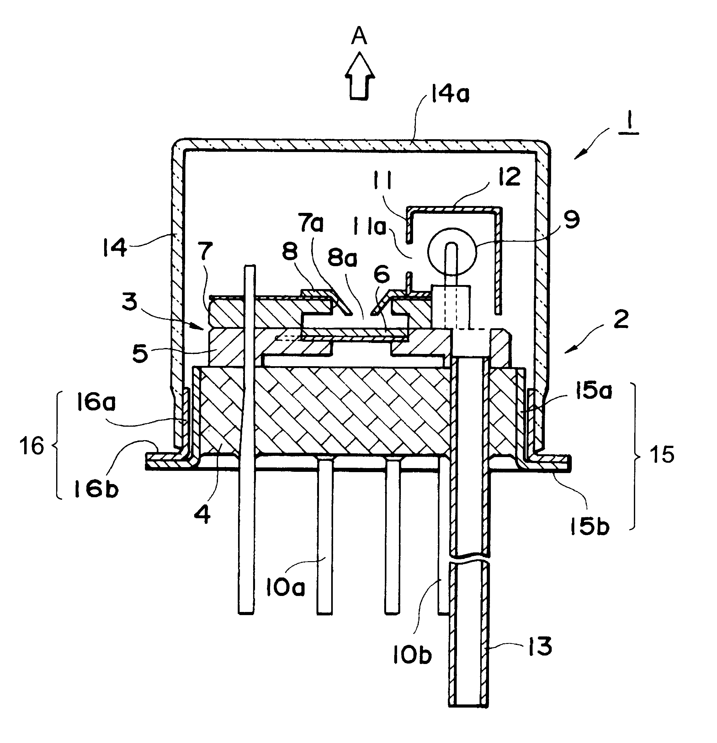
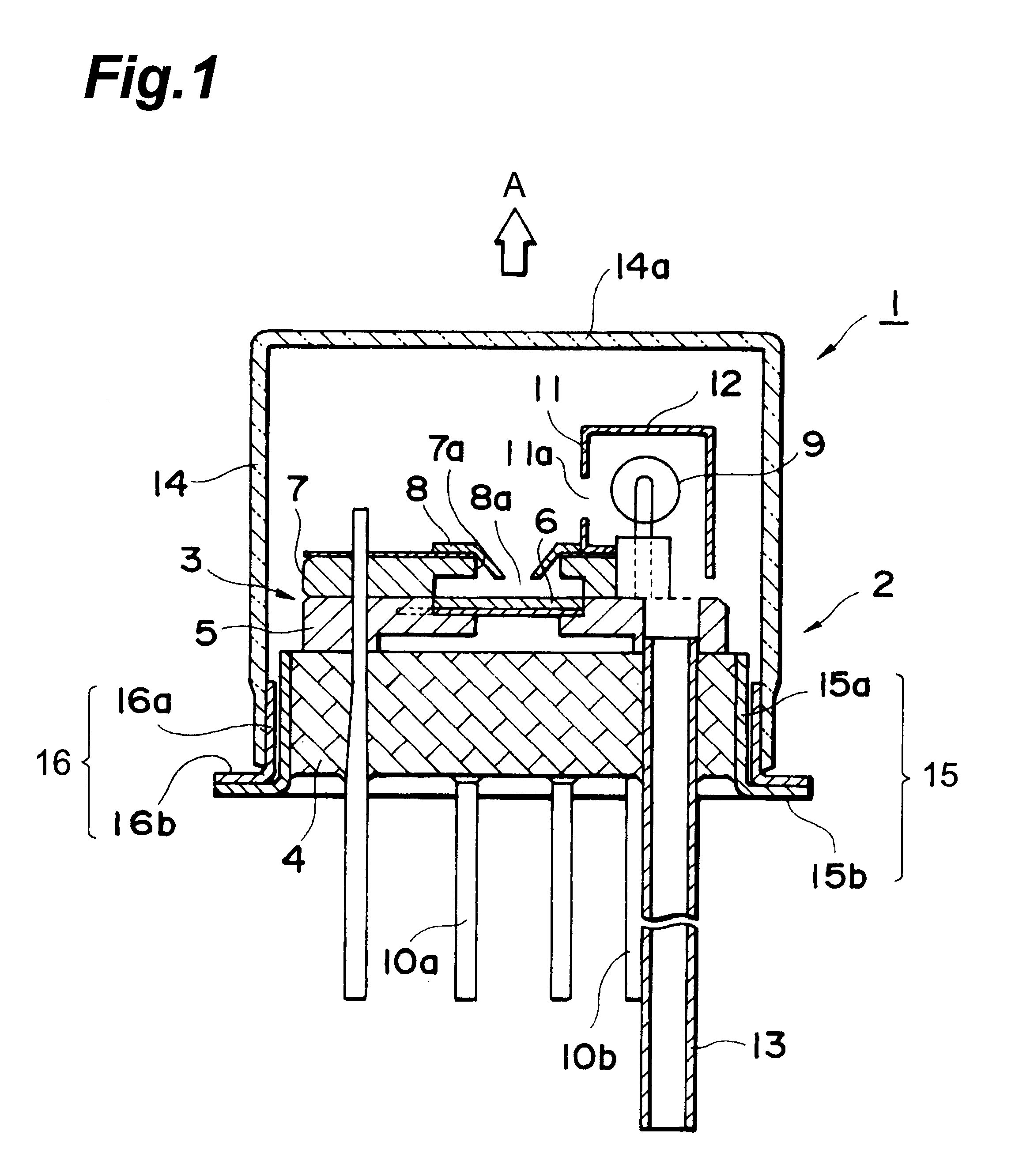
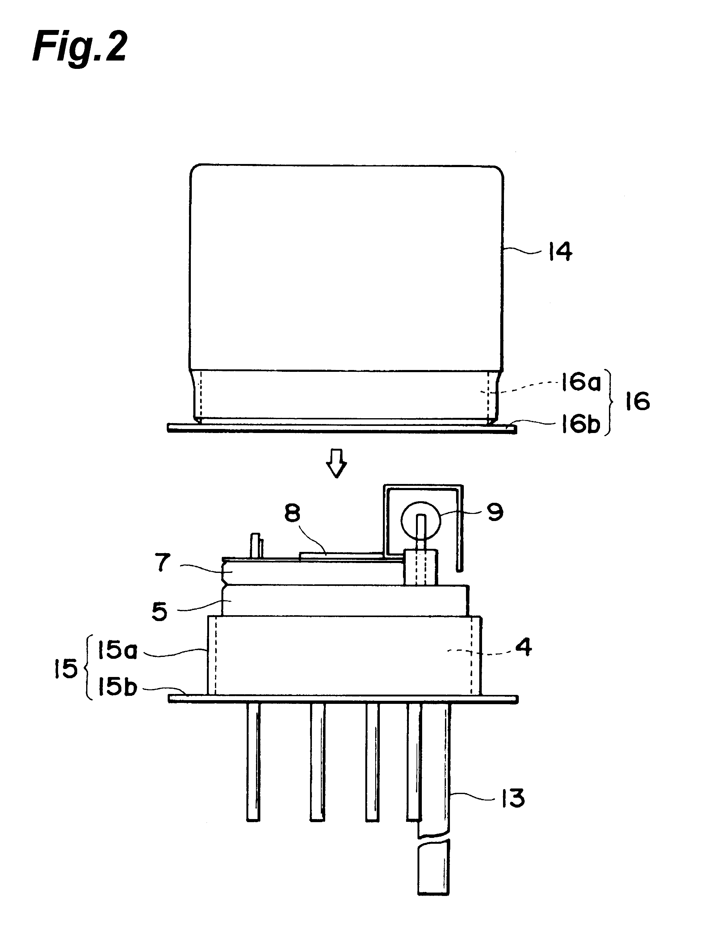
In the following, preferred embodiments of the gas discharge tube in accordance with the present invention will be explained in detail with reference to the accompanying drawings. To facilitate the comprehension of the explanation, the same reference numerals denote the same parts, where possible, throughout the drawings, and a repeated explanation will be omitted.

FIG. 1 is a sectional view showing a first embodiment of the gas discharge tube in accordance with the present invention. The gas discharge tube 1 shown in this drawing is a head-on type deuterium lamp and has a sealed envelope 2 filled with about several Torr of deuterium gas, whereas a light-emitting part assembly 3 is contained in the sealed envelope 2. The light-emitting part assembly 3 has an anode support plate 5 which is made of ceramics and disposed on a stem 4. An anode plate 6 is disposed on the anode support plate 5, so as to be spaced from the stem 4. The anode plate 6 is welded and secured to the upper end of ...


PUM


Abstract

In the gas discharge tube of the present invention, for elongating the life of the discharge tube itself while lowering the assembling temperature, a side tube itself is formed from glass, and a metal is employed in a joint between a stem and the side tube. Namely, a metal-made first peripheral portion provided in the stem and a metal-made second peripheral portion provided in the side tube are utilized in the joint. As a result, the discharge tube itself can be made smaller.

Description

BACKGROUND OF THE INVENTION1. Field of the InventionThe present invention relates to a gas discharge tube; and, in particular, to a gas discharge tube for use as a light source for a spectroscope, chromatography, or the like.2. Background ArtAs techniques in such a field, those disclosed in Japanese Patent Application Laid-Open Nos. HEI 7-326324 and HEI 8-222185 have conventionally been known. In the gas discharge tubes described in these publications, a sealed envelope is constituted by a side tube made of glass and a stem made of glass. Respective stem pins securing anode and cathode sections are plugged in the stem. This sealed envelope is filled with about several Torr of deuterium gas, for example. Such a gas discharge tube is known as a deuterium lamp and is utilized as a stable UV light source.SUMMARY OF THE INVENTIONSince the conventional gas discharge tubes are configured as mentioned above, however, there have been problems as follows.Namely, since the above-mentioned seal...

Claims


Application Information

Patent Timeline
Patent Type & Authority Patents(United States)
IPC IPC(8): H01J61/04H01J61/00H01J61/30H01J61/35H01J63/00H01J63/02H01J61/68H01J63/08H01J61/10
CPCH01J61/10H01J61/30H01J61/302H01J63/08H01J61/68H01J63/02H01J61/35
Inventor IKEDO, TOMOYUKIADACHI, KOUZOUITO, YOSHINOBUMATUI, RYOTARO
Owner HAMAMATSU PHOTONICS KK
Why Eureka
Try Eureka