High-power directional coupler and method for fabricating

a directional coupler and high-power technology, applied in the field of directional couplers, can solve the problems of large amount of labor involved in assembling, high-power couplers on the order of several hundred dollars, and the final tolerances of the geometry of the coupled arms in traditional machined metal high-power couplers are relatively loos

Inactive Publication Date: 2003-06-03
AGILENT TECH INC
View PDF6 Cites 6 Cited by
  • Summary
  • Abstract
  • Description
  • Claims
  • Application Information

AI Technical Summary

Benefits of technology

Since the through arm has metal plated onto the edges, as well as the top and the bottom, the dielectric material is completely enclosed in metal. As a result, the RF fields flow primarily on the metal (outside of the dielectric), and generally do not penetrate into the dielectric. Therefore, the performance of the coupler is independent of the dielectric material's properties (e.g., loss tangent, dielectric constant, etc.). Thus, the coupler has a low insertion loss, enabling the coupler to operate at high-power. In addition, variations in the dielectric material's properties do not effect the performance of the coupler. Therefore, the coupler is more repeatable with improved performance characteristics. Furthermore, the independence of the dielectric material with respect to the coupler performance allows an inexpensive dielectric, e.g., FR4, to be used.

Problems solved by technology

An extensive amount of labor is usually involved in assembling the large number of machined metal parts required for such high-power directional couplers.
The machined metal parts taken in conjunction with the amount of labor have resulted in expensive high-power couplers on the order of several hundred dollars.
Furthermore, the final tolerances for the geometry of the coupled arms in traditional machined metal high-power couplers are relatively loose, due to the large number of separate machining and assembly steps.
The inclusion of a tuning slug further increases the cost of these traditional machined metal high-power couplers.
High-power directional couplers are especially expensive when compared with low power couplers.
However, it has not proved practical to construct high-power directional couplers on printed circuit boards in microstrip or stripline configurations due to the insertion loss in the dielectric printed circuit board material.
The dielectric material typically has inherent losses, which increases the insertion loss of the coupler.
In addition, as the dielectric constant of the dielectric printed circuit board material becomes higher than that of air, the transmission lines of the through and coupled arms of the coupler become correspondingly narrowed, further increasing the insertion loss of the coupler.
Therefore, in the past, printed circuit board designs have been inappropriate for high-power couplers.
In addition, variations in the dielectric material's properties do not effect the performance of the coupler.
For example, machined metal high-power directional couplers typically require expensive connectors and cables to connect to additional circuitry, whereas high-power directional couplers fabricating from printed circuit board material can be easily integrated with microstrip circuitry, such as switches and resistors.

Method used


Image

  • High-power directional coupler and method for fabricating
  • High-power directional coupler and method for fabricating
  • High-power directional coupler and method for fabricating

Examples


Embodiment Construction

The numerous innovative teachings of the present application will be described with particular reference to the exemplary embodiments. However, it should be understood that these embodiments provide only a few examples of the many advantageous uses of the innovative teachings herein. In general, statements made in the specification do not necessarily delimit any of the various claimed inventions. Moreover, some statements may apply to some inventive features, but not to others.

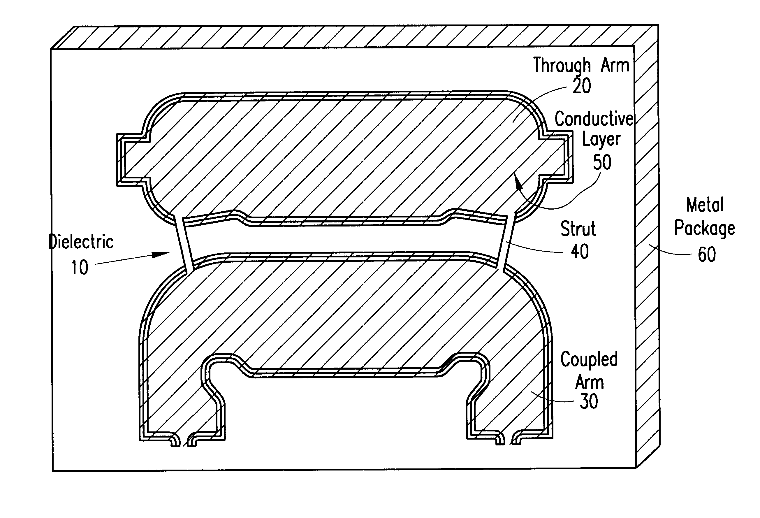
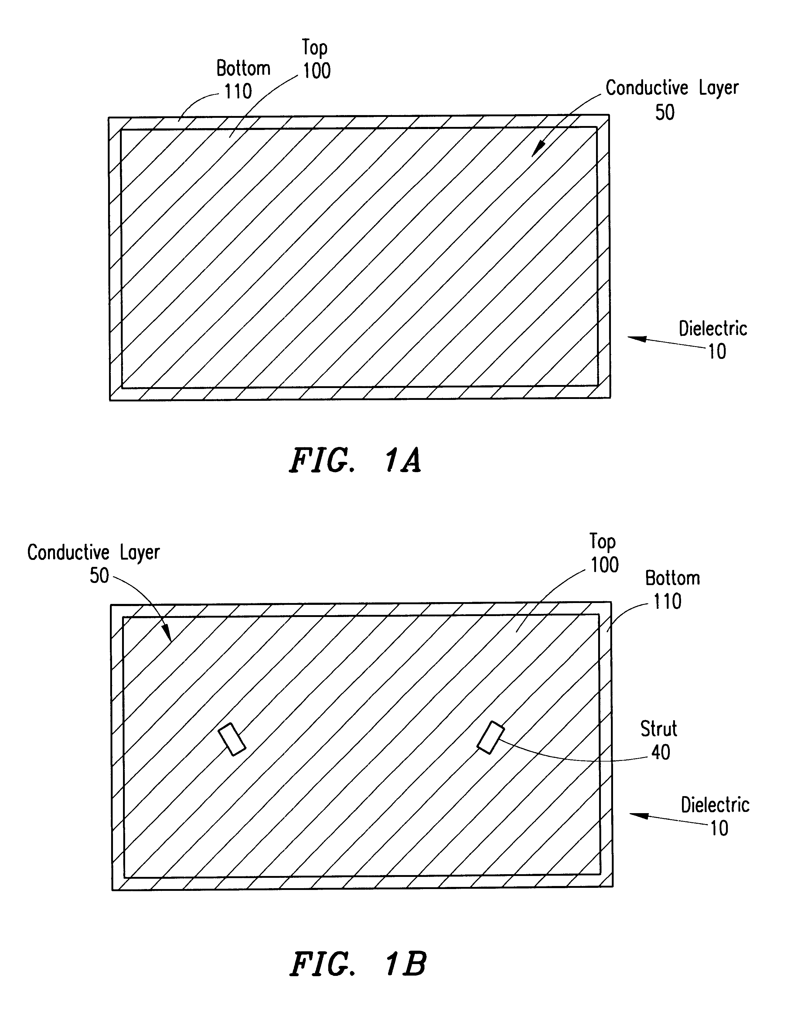
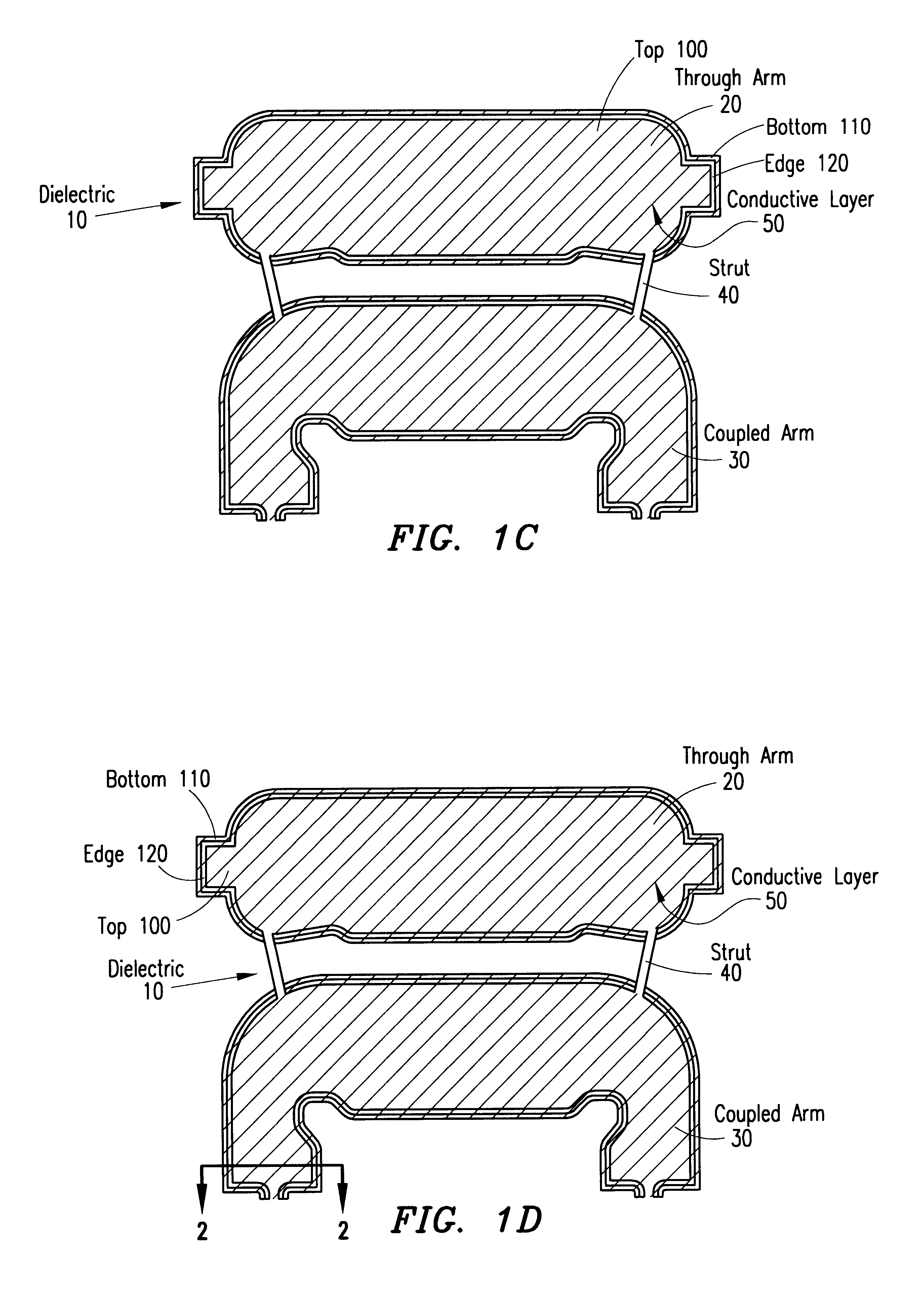
A high-power directional coupler with improved performance can be fabricated at a low cost as shown in FIGS. 1A-1E. The high-power directional coupler is capable of operating up to at least 200 watts. The center conductors, which include, e.g., the through arm 20 and coupled arm 30 shown in FIG. 1C, of the high-power directional coupler are formed from a substrate 10, such as a printed circuit board formed of dielectric material. In some embodiments, the printed circuit board 10 may have a thickness of 0.060 i...


PUM


Abstract

A high-power coupler formed from a substrate, such as a dielectric printed circuit board, is disclosed. The through arm and coupled arm(s) of the coupler have a conductor plated on the top, bottom and edges of the dielectric printed circuit board, completely enclosing the dielectric material in the conductor. A metal package surrounding the coupler forms the outer ground. Thin non-conductive struts of the dielectric material of the printed circuit board interconnect the separate arms of the coupler. The coupler may be integrated with microstrip circuitry, such as switches and resistors.

Description

1. Technical Field of the InventionThe present invention relates generally to directional couplers, and specifically to high-power directional couplers.2. Description of Related ArtA directional coupler has a through arm through which a signal passes and at least one coupled arm that samples the signal. At a basic level, a high-power directional coupler causes a sample of an electromagnetic wave propagating on the through arm to propagate on the coupled arm. Therefore, the coupled arm serves to sample the signal on the through arm. A directional coupler is capable of sampling signals propagating in two different directions. A signal flowing in a first direction on the through arm is sampled on one port of the coupled arm, while a signal flowing in the opposite direction is sampled on the other port of the coupled arm.To measure output power or other high-power signals in a system, high-power handling capability is desirable for dual directional couplers. For example, dual directiona...

Claims


Application Information

Patent Timeline
Patent Type & Authority Patents(United States)
IPC IPC(8): H01P11/00H01P5/16H01P5/18
CPCH01P11/00H01P5/185
Inventor NOE, TERRENCE R.
Owner AGILENT TECH INC
Why Eureka
Try Eureka