

Method and apparatus for encoding digital data
a digital data and digital data technology, applied in the field of digital data encoding, can solve the problems of complex structure of the modulation apparatus and the complex structure of the apparatus for carrying out the modulation procedur
- Summary
- Abstract
- Description
- Claims
- Application Information
AI Technical Summary
Benefits of technology
Problems solved by technology
Method used
Image

Examples
first embodiment
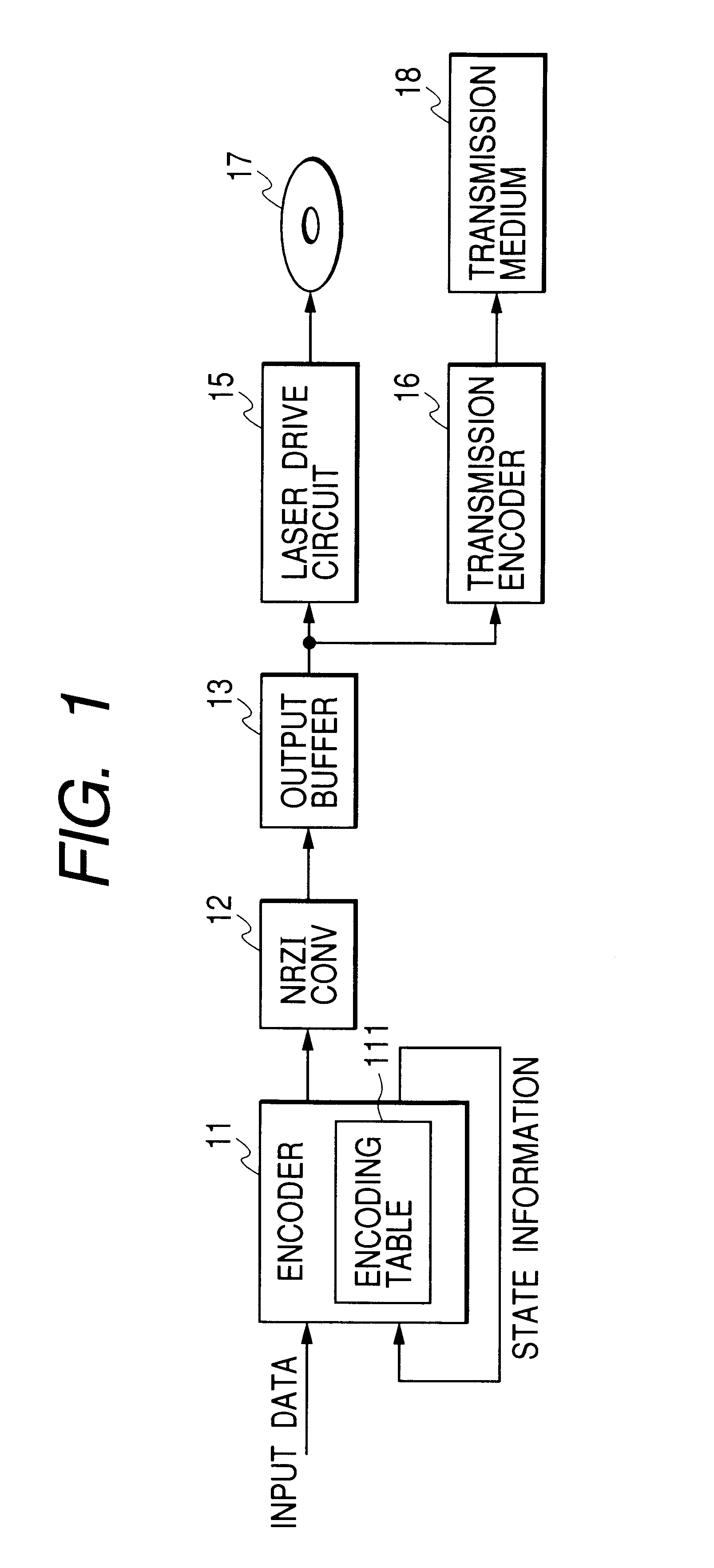
FIG. 1 shows an encoding apparatus according to this invention. As shown in FIG. 1, the encoding apparatus includes an encoder 11, an NRZI (non-return-to-zero invert) converter 12, and an output buffer 13 which are sequentially connected in that order. The output buffer 13 is followed by a laser drive circuit 15 and a transmission encoder 16.
The encoder 11 may be formed by a digital signal processor, a CPU, or a similar device including a combination of an input / output port, a processing section, a ROM, and a RAM. In this case, the encoder 11 operates in accordance with a control program stored in the ROM or the RAM. The control program is designed to enable the encoder 11 to implement operation steps mentioned hereafter.
The encoder 11 receives input data (an input digital signal) in the form of, for example, a bit stream. The device 11 encodes the input data by referring to encoding tables 111. The encoding by the encoder 11 conforms to RLL (1, 7) which means prescribed run length ...
second embodiment
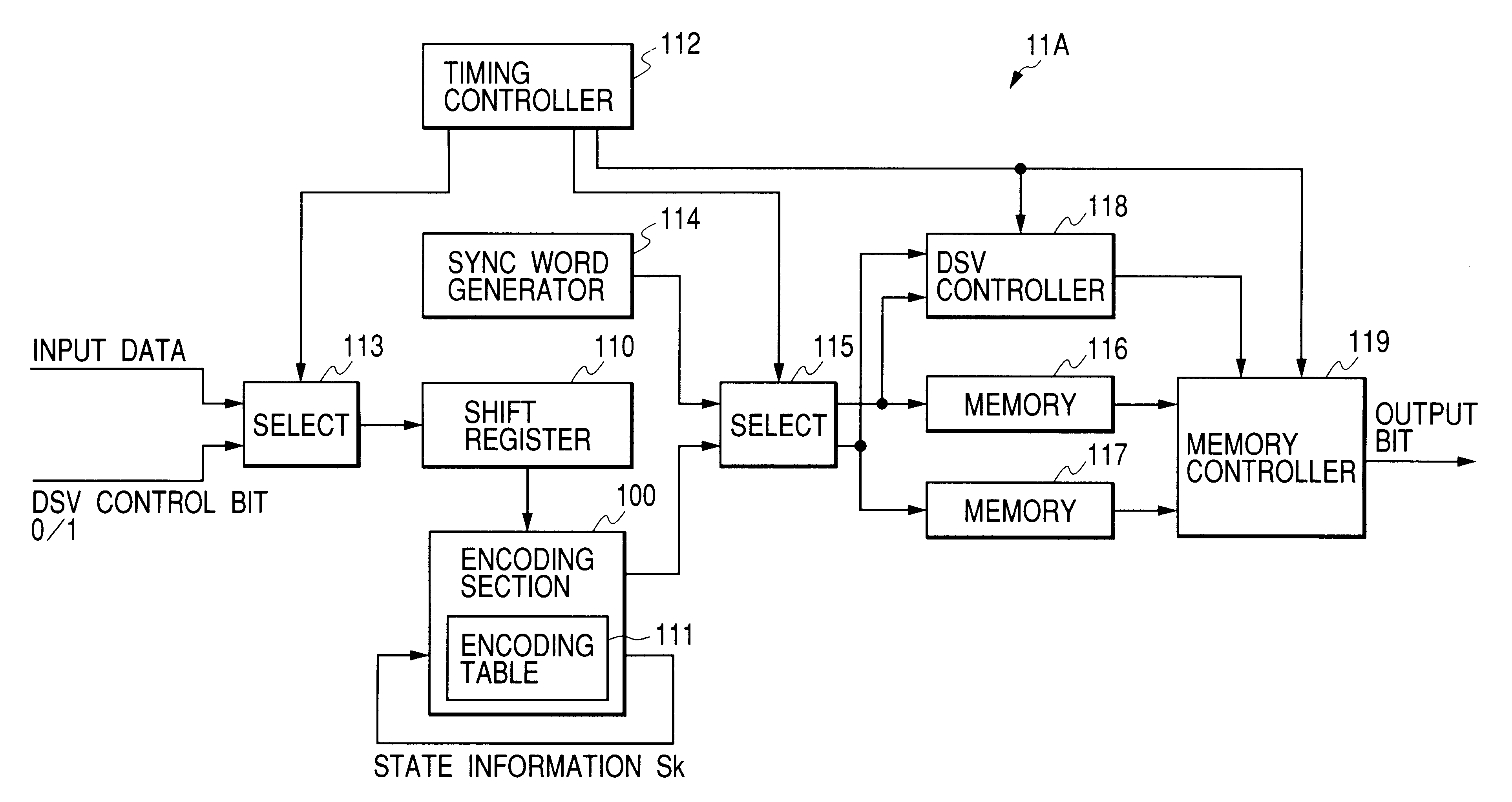
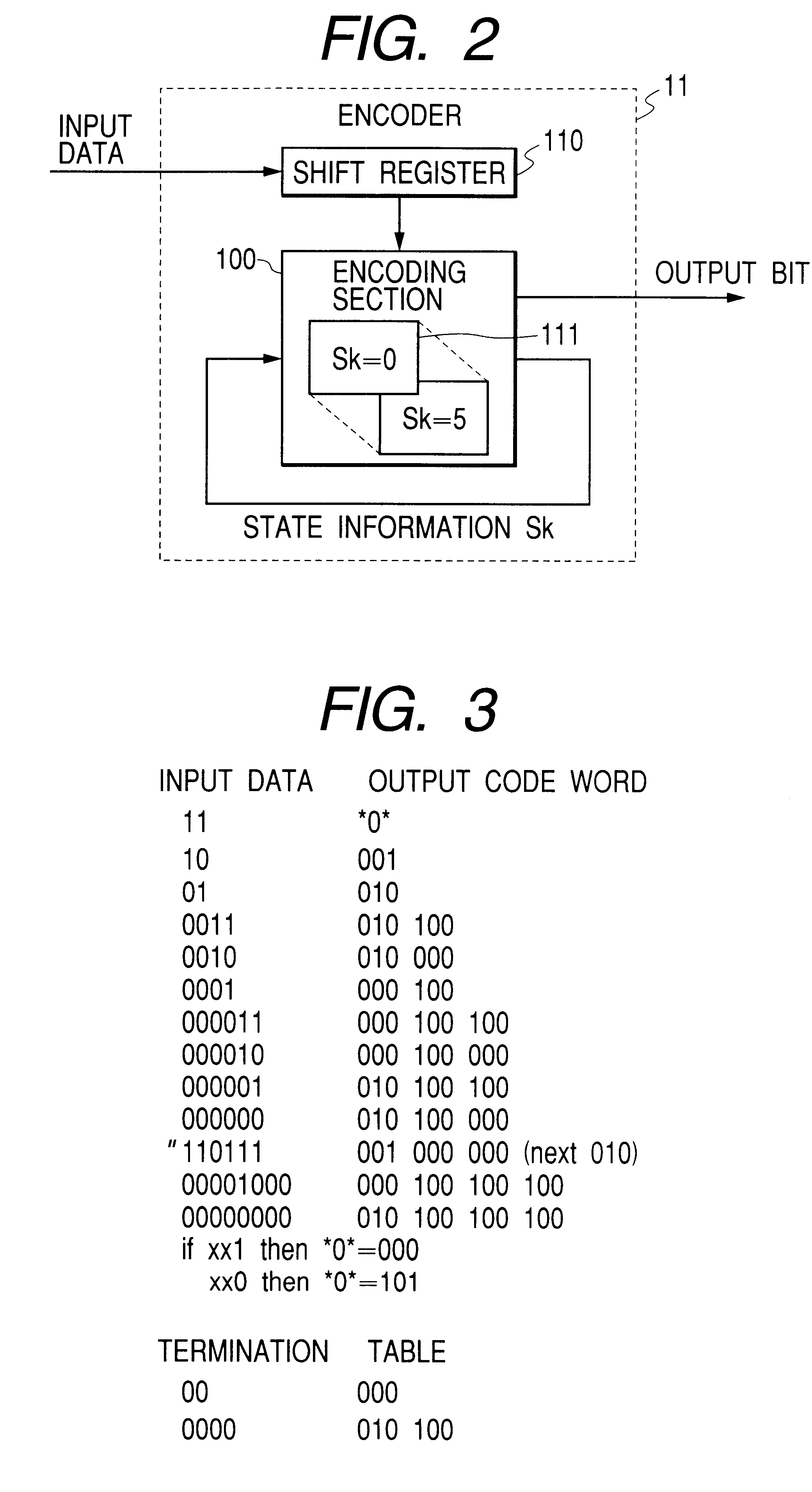
FIG. 12 shows an encoder 11A in a second embodiment of this invention. The encoder 11A may replace the encoder 11 in the encoding apparatus of FIG. 1. As shown in FIG. 12, the encoder 11A includes an encoding section 100 and a shift register 110 which are similar to those in the encoder 11 (see FIG. 2).
The encoder 11A further includes a timing controller 112 and a selector 113. The selector 113 receives input data. The selector 113 receives a signal of "0" and a signal of "1" as a DSV control bit of "0" and a DSV control bit of "1" respectively. The timing controller 112 is driven by a master clock signal which uses a bit sync clock signal. The timing controller 112 generates a first control signal in response to the master clock signal. The timing controller 112 feeds the first control signal to the selector 113. The device 113 selects the input data or the DSV control bit "0" in response to the first control signal, and passes the selected input data or the selected DSV control bi...
third embodiment
A third embodiment of this invention is similar to the first or second embodiment thereof except for design changes mentioned hereafter. The third embodiment of this invention includes "M" encoding tables, where "M" denotes a predetermined natural number equal to or greater than 2. According to the "M" encoding tables, every m-bit piece of input data is encoded into an n-bit output code word, where "m" and "n" denote predetermined natural numbers. Thus, the input data are encoded into a stream of n-bit output code words. This encoding resembles fixed-length block encoding. Generally, the number "n" is greater than the number "m". Ones or more of n-bit output code words form general output code words classified according to constraint length. A sync word is periodically inserted into the output-code-word stream to generate a sync-added output-code-word stream. Termination processing is implemented to terminate a general output code word at the end of every sync frame. In addition, DS...
PUM
 Abstract
Description
Claims
Application Information