Bayonet locking system and method for vending machines and the like

a technology of locking system and bayonet, which is applied in the direction of keyhole guards, mechanical control devices, instruments, etc., can solve the problem of failure to provide a lock assembly

Inactive Publication Date: 2003-06-24
TRITEQ LOCK & SECURITY L L C
View PDF22 Cites 83 Cited by
  • Summary
  • Abstract
  • Description
  • Claims
  • Application Information

AI Technical Summary

Benefits of technology

A related object of the present invention is to provide a bayonet locking system and method for locking and unlocking vending machines or the like in a novel and secure manner.
FIG. 12, item 2d is provided as mounting surfaces for FIG. 11 Item 4. Surface 4a as mounted into Item 2 provide guiding for Items 21 and then translated through to Item 22. Areas Item 4d correspond to Item 2d FIG. 9 Area 2a has a steel reinforced arrangement to prevent deformation of the plastic as it ages.

Problems solved by technology

The prior art, however, failed to provide a lock assembly which automatically pulls the door of a vending machine into a completely closed position against the housing and / or a lock assembly which utilizes a remotely controlled electronic latching mechanism to lock and unlock the door.

Method used


Image

  • Bayonet locking system and method for vending machines and the like
  • Bayonet locking system and method for vending machines and the like
  • Bayonet locking system and method for vending machines and the like

Examples


Embodiment Construction

Locked to Unlocked:

In controlling the motor to change the state of the lock from locked to unlocked, the controller must first receive a valid access control signal from the operator (via a secure access control input means such as a keypad or hand-held transmitter) and shall proceed to energize the motor in the forward direction. The controller will wait for a position feedback indicator (SW1) which is measured by the controller CPU to determine the lock has landed in the unlocked state. If this sensor is closed, the controller will proceed to break and de-energize the motor. In case the SW1 sensor is failed, the controller uses a motor current feedback signal to detect end of worm gear travel by sensing a stall motor condition and to de-energize the motor. In case both sensors fail, the controller will discontinue operation based on elapsed time.

In the case an over-current signal is received, the controller must determine if this signal is a function of a jammed bayonet with the l...


PUM


Abstract

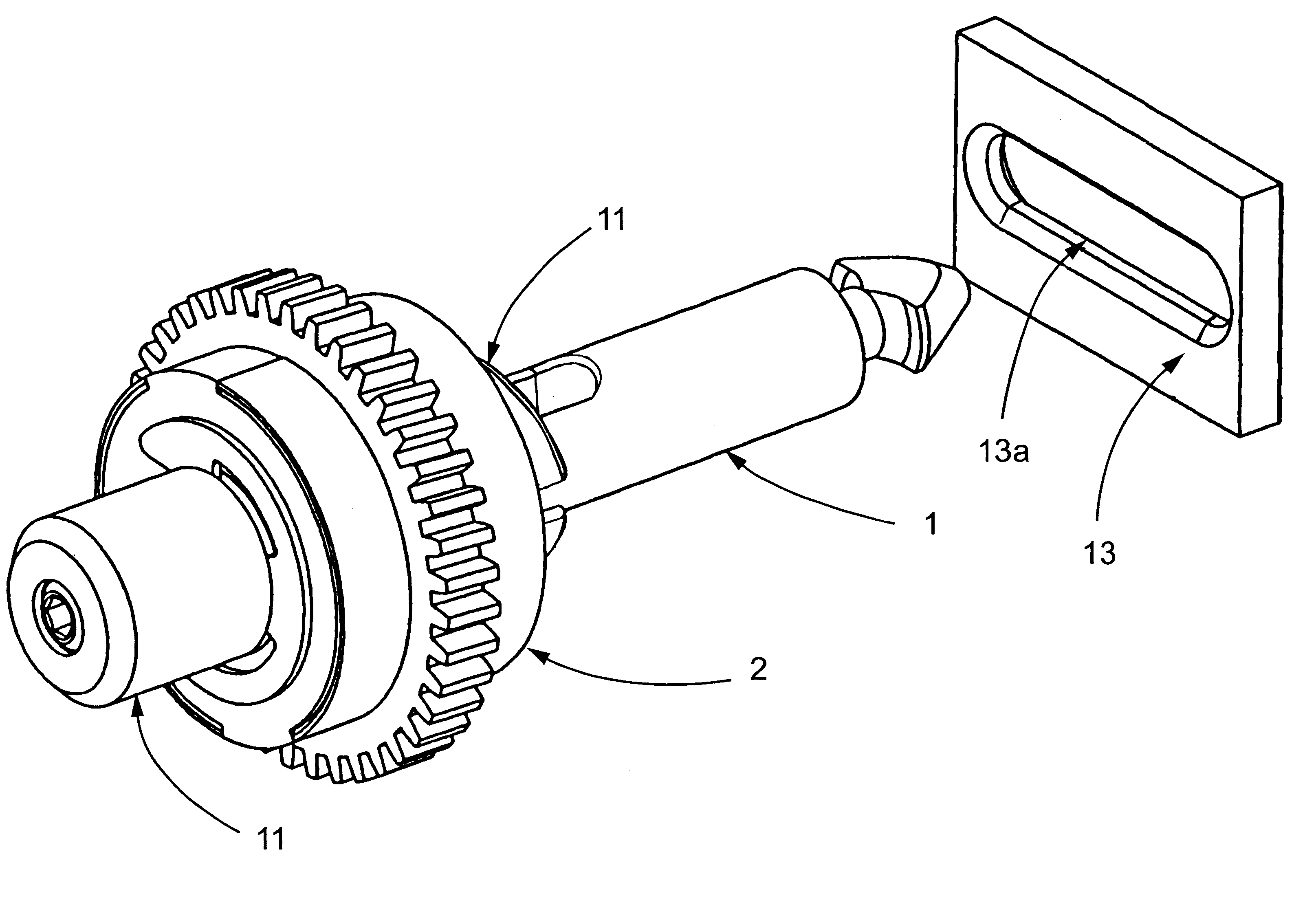
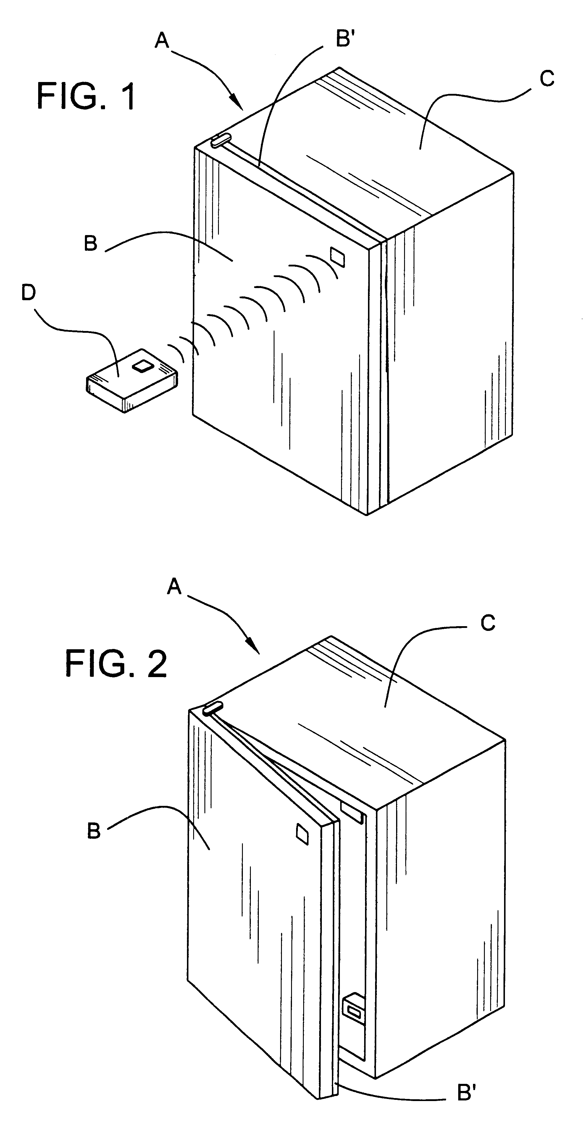
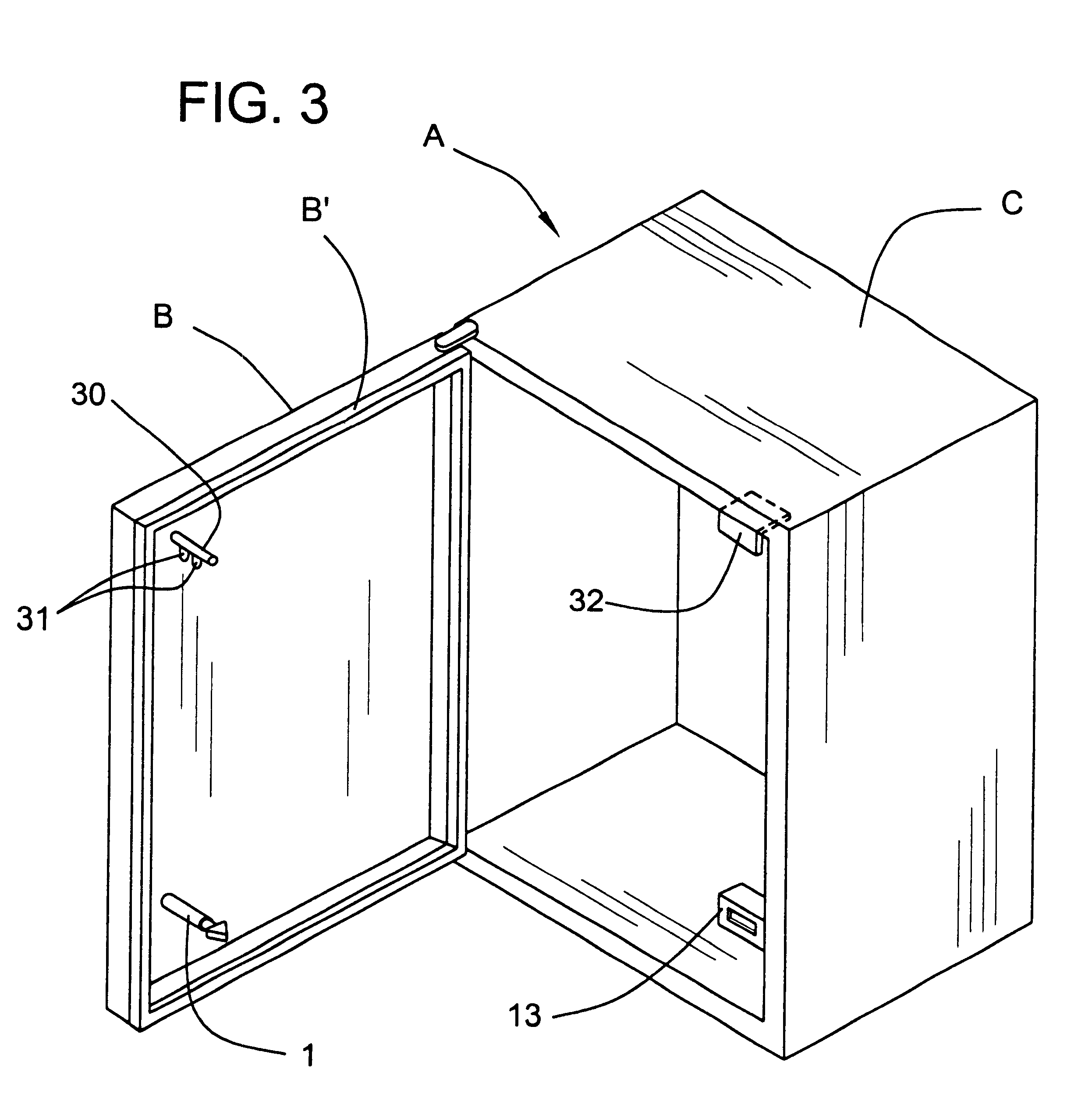
A bayonet locking system for vending machines is provided to lock and unlock the machine preferably with a remotely controlled electronic operating unit. It includes at least one motor driven axially and rotationally movable bayonet with an enlarged shaped head being mounted preferably on a gasketed door and at least one receptacle receiving device disposed within the machine interior positioned for engagement by the bayonet when the door is moved to an intermediate position. The bayonet advances into the receptacle and rotates to capture it in the receptacle and then axially retracts to pull the door into the closed position wherein a gasket disposed between the door and the machine is substantially uniformly compressed and sealed around its periphery. An axially rotatable pin with fins may be used with a bracket on either the door or machine to prevent prying of the door at opposite corners.

Description

The present invention relates generally to locking devices and, more particularly, to a bayonet locking system for vending machines and the like and a method for locking and unlocking the same.In various machines such as vending machines, food machines, candy machines, refrigerated drink machines, and the like, there is ordinarily provided a lock assembly to prevent unauthorized access to the contents thereof. For example, some vending machines are provided with a key-activated lock assembly such as a pop-out T-handle lock assembly which allows an authorized user to open the door of the vending machine with a properly-encoded key. Such T-handle lock assemblies are well known in the art, as evidenced by numerous patents including U.S. Pat. No. 3,089,330 (Kerr), U.S. Pat. No. 3,550,412 (Pitel et al.), U.S. Pat. No. 4,552,001 (Roop), U.S. Pat. No. 4,760,721 (Steinbach), U.S. Pat. No. 4,899,561 (Myers), and U.S. Pat. No. 5,548,982 (Rawling). With such lock assemblies, the door is initia...

Claims


Application Information

Patent Timeline
Patent Type & Authority Patents(United States)
IPC IPC(8): E05B17/00E05B63/00E05B63/12
CPCE05B17/0029E05B47/0012E05B47/023G07F9/10E05C5/02E05B63/125E05B2047/002E05B2047/0069E05F15/616G07C9/00896G07C2009/00769G07C2209/08E05Y2900/608E05B15/0205E05B47/026E05B2047/0024Y10T70/5761Y10T70/7068Y10T292/1014Y10T292/1021Y10T292/1079Y10T292/1082Y10T292/699
Inventor ROATIS, CALIN VASILEDENISON, WILLIAM D.BARNAS, TOMASZMYERS, GARY L.
Owner TRITEQ LOCK & SECURITY L L C
Why Eureka
Try Eureka