Method and system of flutter control for rotary compression systems

a rotary compression system and aeromechanical technology, applied in mechanical equipment, machines/engines, liquid fuel engines, etc., can solve the problems of aeromechanical instability, flutter imposes constraints on flutter degrades the performance of rotary compressors, etc., to reduce flutter instabilities, facilitate the operation of rotary compressors, and avoid flutter instability characteristics

Inactive Publication Date: 2003-06-24
RTX CORP
View PDF18 Cites 56 Cited by
  • Summary
  • Abstract
  • Description
  • Claims
  • Application Information

AI Technical Summary

Benefits of technology

One advantage of the present invention is to provide a control system that facilitates operation of a rotary compressor at an optimal operating mode, while avoiding the flutter instability characteristics.
is to provide a control system that facilitates operation of a rotary compressor at an optimal operating mode, while avoiding the flutter instability characteristics.
Accordingly, one aspect of the instant invention is drawn to a system for reducing flutter instabilities in a rotary compressor having a plurality of blades that comprises a system for reducing flutter characteristics in a rotary compressor having a plurality of blades comprising:
a plurality of sensors for sensing vibrations resulting from deformation movement of the blade and generating a flutter signal that is a function of the vibrations;
a signal conditioning circuit, coupled to each of the sensors for receiving the flutter signals and processing the flutter signals to produce a composite signal that is a function of the flutter signals;
a computation circuit, coupled to the signal conditioning circuit, for receiving the composite signal and generating an amplitude signal that is a function of the composite signal;

Problems solved by technology

Flutter is aeromechanical instability that is experienced near the stall line of a performance map due to blade motion.
Flutter imposes constraints on the performance of rotary compressors, such as gas turbine engines.
Flutter instability can degrade the performance of the rotary compressor and may also lead to fatigue failure or other permanent damage to the compressor.
One result of the flutter instability can be blade deformation and / or blade fatigue failure.
Unfortunately, this results in substantial performance penalties for the compressor.
The stall and / or surge approach in the above-cited patent application does not solve the problem of flutter instability.
The blade movement, and associated deformation or deflection of the blade is the source of flutter instability.

Method used


Image

  • Method and system of flutter control for rotary compression systems
  • Method and system of flutter control for rotary compression systems
  • Method and system of flutter control for rotary compression systems

Examples


Embodiment Construction

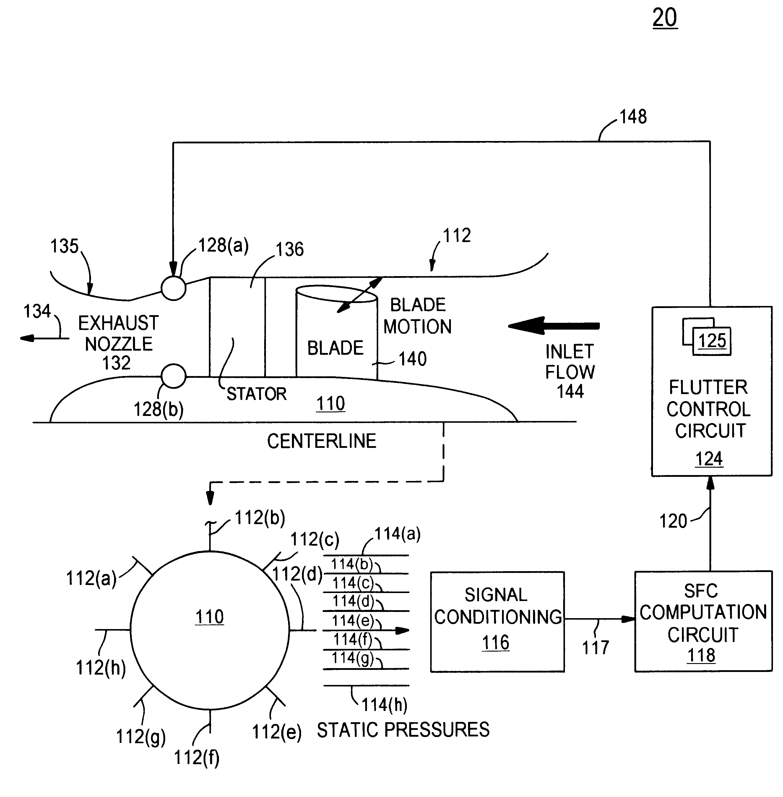
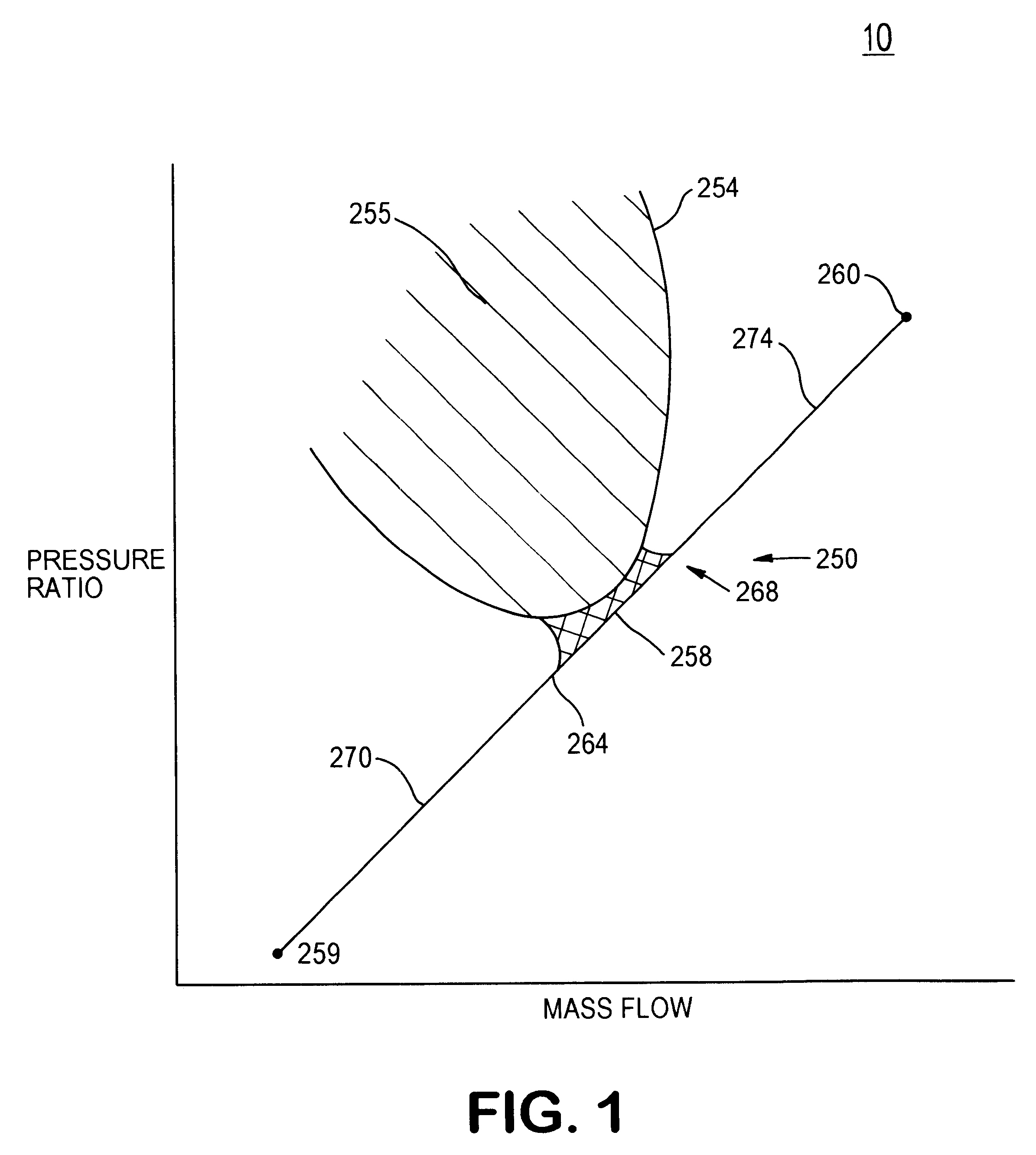
FIG. 1 shows an example of a performance map 10 for a rotary compression system. Although this invention will be described in terms of a rotary compressor for a gas turbine engine, that is suitably mounted to a vehicle, such as an aircraft, it also is equally applicable to other rotary compressors and similar apparatus such as axial flow compressors, industrial fans, centrifugal compressors, centrifugal chillers, and blowers.

The performance map 10 plots mass flow on the X-axis and pressure ratio on the Y-axis. Mass flow is the rate of fluid passing through a compressor per unit time. Pressure ratio is the pressure at the exit nozzle of a compressor divided by the pressure at the inlet of a compressor. The performance map 10 shows an operating line 250 that represents nearly optimal operational characteristics or parameters for a particular rotary compressor. Point 260 on operating line 250 suitably represents a "take off" point, which means the pressure ratio and mass flow relations...


PUM


Abstract

The invention is a method and system for fan flutter control. The output of circumferentially distributed sensors is used to calculate the asymmetry of a flow field. The asymmetry measurement is used to modulate a bleed valve, variable exhaust nozzle or other device to increase the fan's tolerance of flutter disturbances.

Description

1. Field of the InventionThis invention relates generally to a method and system for controlling aeromechanical instabilities (flutter) in rotary compression systems such as aircraft gas turbine engines. More particularly, this invention relates to sensing rotary blade characteristics of a rotary compressor or the flow asymmetry produced by blade movement to minimize flutter instability conditions.2. Brief Description of the ArtFlutter is aeromechanical instability that is experienced near the stall line of a performance map due to blade motion.Flutter imposes constraints on the performance of rotary compressors, such as gas turbine engines. Flutter is caused by blade motion or deflection and can be viewed as a two-dimensional phenomena that results in a region of reduced or reversed fluid flow through the compressor causing the compressor to reduce output. Flutter instability can degrade the performance of the rotary compressor and may also lead to fatigue failure or other permanen...

Claims


Application Information

Patent Timeline
Patent Type & Authority Patents(United States)
IPC IPC(8): F04D27/02F04D29/66
CPCF04D27/0207F04D29/668F05B2270/504F05B2270/108F05B2220/306F05D2270/10F05D2270/54F05D2220/326
Inventor EVEKER, KEVIN M.GYSLING, DANIEL L.NETT, CARL N.
Owner RTX CORP
Why Eureka
Try Eureka