Disk recording system

a recording system and disk technology, applied in the field of disk recording system, can solve the problems of buffer underrun error becoming more likely to occur, discontinuous recording data, and inability to use recording mediums,

Inactive Publication Date: 2003-06-24
SANYO ELECTRIC CO LTD
View PDF18 Cites 48 Cited by
  • Summary
  • Abstract
  • Description
  • Claims
  • Application Information

AI Technical Summary

Problems solved by technology

This write-once medium such as a CD-R, however, has a problem of buffer underruns in which a rate of data transfer for inputting data to a buffer does not keep up with a rate of data transfer for recording data on the medium, and this in turn leads to buffer underrun errors which cause the recorded data to be discontinuous.
In the case of disc-at-once or track-at-once medium in which file groups to be written are previously designated, the recording medium cannot be used when such a buffer underrun error occurs.
Such buffer underrun error has become more likely to occur as the recording rate in CD-R drives has increased to

Method used


Image

  • Disk recording system
  • Disk recording system
  • Disk recording system

Examples


Embodiment Construction

The preferred embodiment of the present invention will be described in further detail with reference to the accompanying drawings.

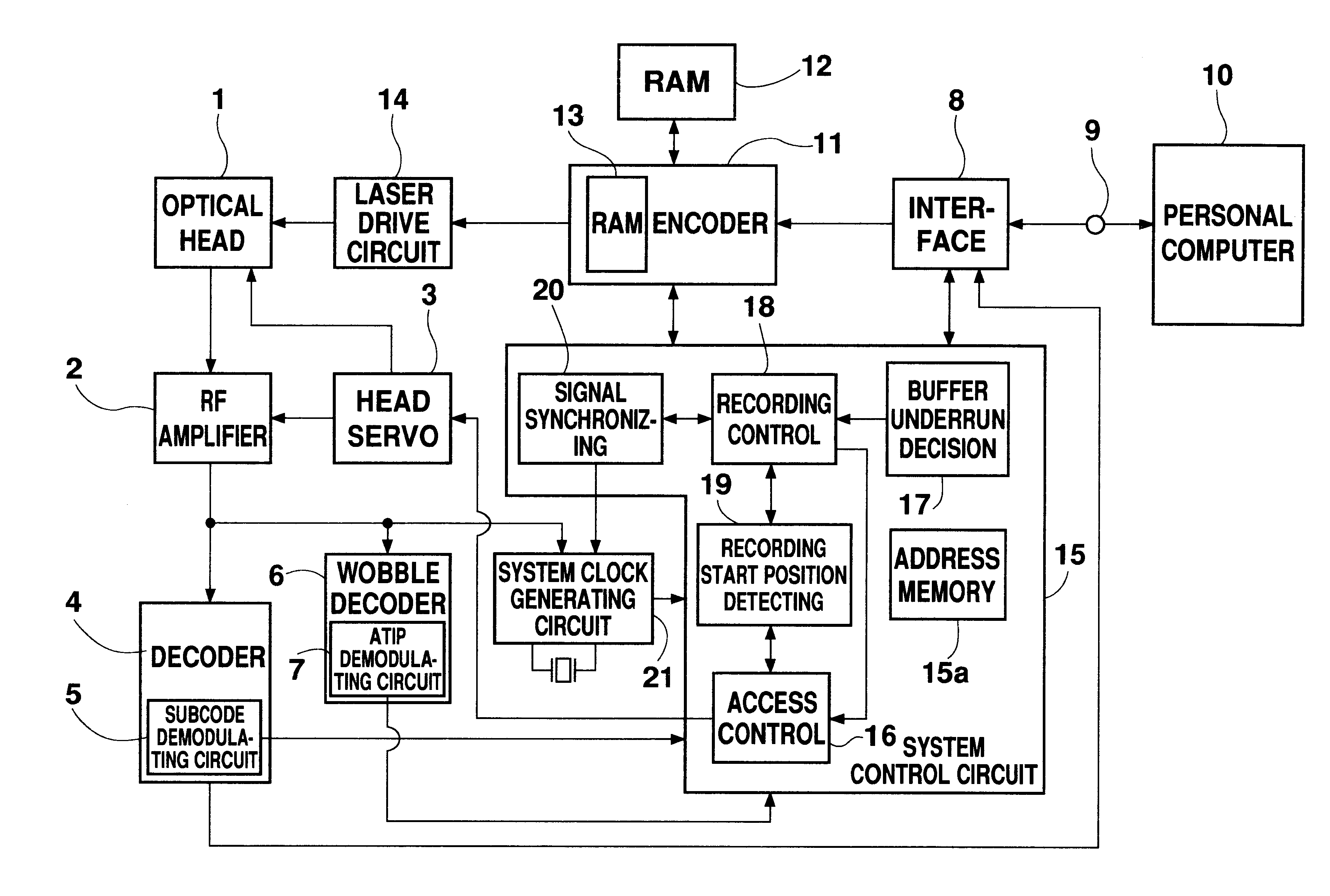
FIG. 1 is a block circuit diagram showing an example of a CD-R drive of a disk recording system according to the present invention.

In FIG. 1, reference numeral 1 denotes an optical head which irradiates a laser beam to trace a disk for writing / reading data onto / from the disk, while numeral 2 denotes an RF amplifier for amplifying an RF signal (a high frequency signal) obtained from the optical head which reads recorded data on the disk, and for coding the RF signal as binary data to be then output as digital data. Reference numeral 3 denotes a head servo which performs focusing control for feeding back an output of the optical head 1 via the RF amplifier 2 so as to focus a laser beam on a signal surface of the disk and tracking control so that the laser beam will follow a signal track of the disk, as well as thread feeding control for moving the optical h...


PUM


Abstract

When a buffer underrun decision circuit decides that a buffer underrun is about to occur, data recording on the disk is interrupted by a recording control circuit. On the other hand, when the buffer underrun decision circuit determines that a buffer underrun situation has been avoided, data recording is resumed by the recording control circuit. At this time, data recording is resumed from a position of the disk which is continuous to data recorded by the time the data recording was interrupted, thereby recording new data continuous to the last recorded data.

Description

1. Field of the InventionThe present invention relates to a disk recording system which allows data to be recorded in addition to already recorded data, and relates in particular to a disk recording system which ensures continuity of recorded data even when buffer underruns occur.2. Description of Related ArtAn optical disk recording system for recording data on a disk has been known in which a light beam is irradiated from an optical head onto a disk to change the reflectivity of a recording layer of the disk and thereby record data on the disk. Among such optical disk recording systems, a CD-R (recordable) drive of the CD (Compact Disc) family is a well known example in which a write-once medium that prohibits physical erasure of already recorded data is employed.This write-once medium such as a CD-R, however, has a problem of buffer underruns in which a rate of data transfer for inputting data to a buffer does not keep up with a rate of data transfer for recording data on the med...

Claims


Application Information

Patent Timeline
IPC IPC(8): G11B20/10G11B19/04G11B7/00G11B7/0045
CPCG11B19/04G11B20/10527G11B2020/10814G11B7/00
Inventor TSUKIHASHI, AKIRA
Owner SANYO ELECTRIC CO LTD
Why Eureka
Try Eureka