Wound field synchronous machine control system and method

a synchronous machine and control system technology, applied in the direction of motor/generator/converter stopper, electric generator control, dynamo-electric converter control, etc., can solve the problems of inflexible modification of analog circuitry of conventional techniques, non-linear and highly sensitive gain of circuitry, and limitations on the outer control loop

Inactive Publication Date: 2003-07-01
GE GLOBAL SOURCING LLC
View PDF11 Cites 32 Cited by
  • Summary
  • Abstract
  • Description
  • Claims
  • Application Information

AI Technical Summary

Problems solved by technology

Thyristor based (or other phase control based) rectification experiences inherent non-linear behavior, and thus control presents several control challenges.
The analog circuitry of conventional techniques is inherently inflexible to modifications in that any design changes require hardware changes.
Additionally, the gain of the circuitry is non-linear and highly sensitive to the operating point of the firing angle, the speed of the alternator, the level of field excitation, and the load variation.
This relation imposes limitations on the outer control loops in that the bandwidths must be significantly lower (typically on the order of about ten) than the pulse frequency.
The outer control loops must be stabilized for all operating points, which means that performance will be compromised to ensure stability at the worst case operating points.

Method used


Image

  • Wound field synchronous machine control system and method
  • Wound field synchronous machine control system and method
  • Wound field synchronous machine control system and method

Examples


Embodiment Construction

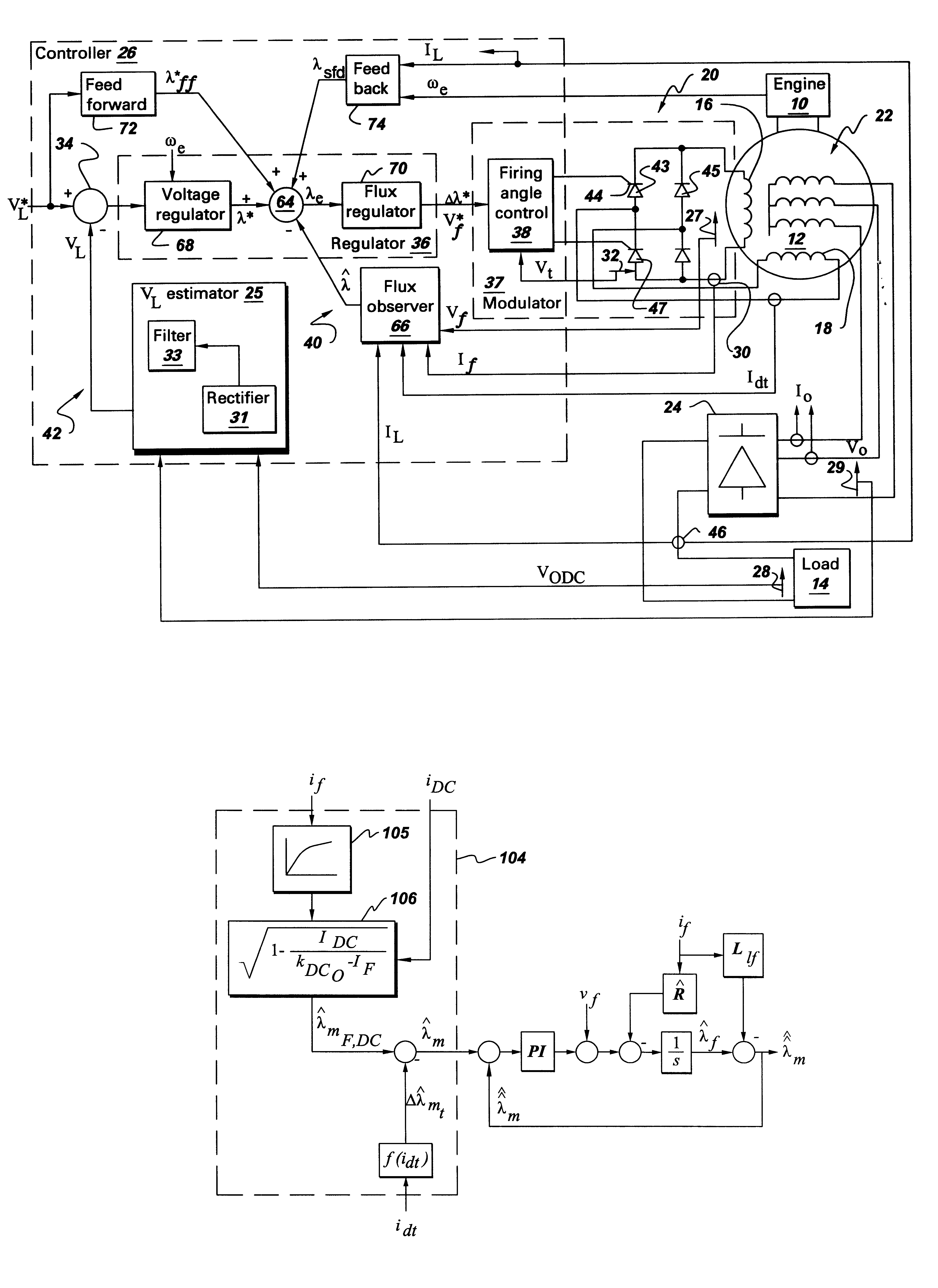
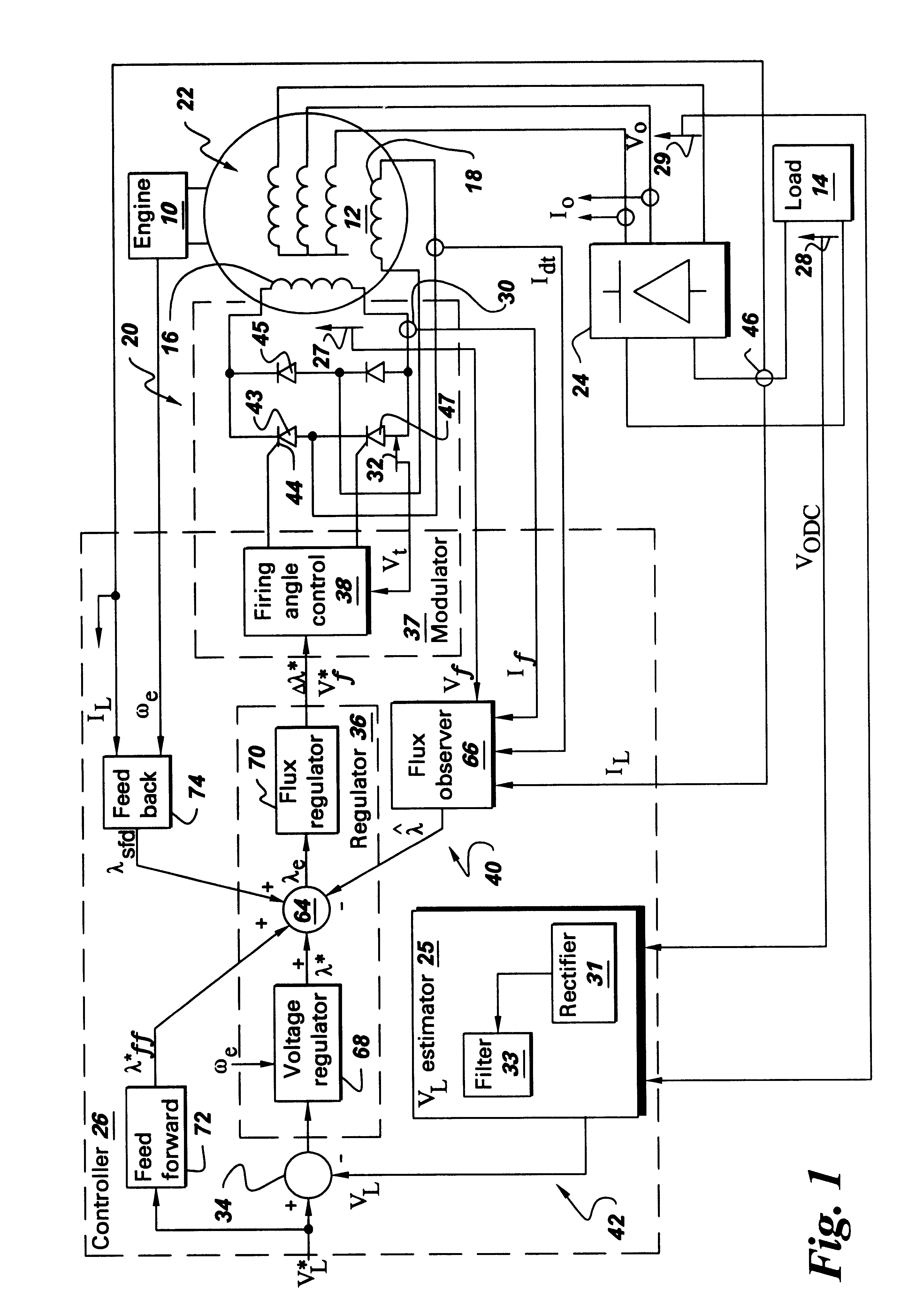
FIG. 1 is a block diagram of a control system 52 in accordance with several embodiments of the present invention which may be used individually or in combination. As discussed above, the control system provides a regulated DC voltage for powering a load 14 which, in one embodiment, comprises a traction vehicle's motor drive system. A wound field synchronous machine 12 such as an alternator, for example, is mechanically driven from a prime mover 10 such as an engine, over a range of speed. The machine field is electrically excited from a battery source (not shown) during start-up and electrically self-excited from an auxiliary (tertiary) winding 18 during normal operation.

A phase-controlled rectifier 20, such as a thyristor bridge, for example, is used to self-excite a machine field winding 16 by rectifying the AC auxiliary voltage and applying the resulting DC voltage to the field winding. In one embodiment, phase-controlled rectifier 20 comprises a silicon controlled rectifier brid...


PUM


Abstract

A wound field synchronous machine control system comprises: an auxiliary winding for obtaining auxiliary AC voltage from the wound field synchronous machine; a phase controlled rectifier for rectifying the auxiliary AC voltage and supplying rectified DC voltage to the wound field synchronous machine; and a controller. The controller is configured for using a voltage signal across the auxiliary winding to obtain volt-second values of the auxiliary winding and using the volt-second values for firing angle control of switches of the phase controlled rectifier. Alternatively or additionally, the controller is configured for obtaining airgap flux values of the wound field synchronous machine and using the airgap flux values for firing angle control of switches of the phase controlled rectifier.

Description

The invention relates generally to field regulation of wound field synchronous machines and more particularly to off-highway vehicle alternator controls.Self-propelled traction vehicles such as large off-highway haulage trucks include electric propulsion systems. A typical propulsion system, such as described in commonly assigned Black et al., U.S. Pat. No. 4,495,449, includes an operator-controlled throttle adapted to control the rotational speed of a prime mover which may, for example, comprise a diesel engine. An output shaft of the prime mover is drivingly coupled to a rotor of an alternating current (AC) generator (a wound field synchronous machine commonly referred to as an alternator) which has a set of three-phase main windings, an auxiliary (tertiary) winding, and a field winding. The three-phase, generally sinusoidal, alternating voltage that is generated in the main windings of the alternator is converted to direct voltage by means of an uncontrolled full-wave rectifying ...

Claims


Application Information

Patent Timeline
Patent Type & Authority Patents(United States)
IPC IPC(8): B60L11/02H02P9/30H02P9/14B60L50/10
CPCB60L11/02H02P9/305B60L2210/20B60L2220/14Y02T10/70Y02T10/7077Y02T10/725Y02T10/642B60L50/10Y02T10/64Y02T10/7072Y02T10/72
Inventor GARRIGAN, NEIL RICHARDYOUNG, HENRY TODDJONES, BRADLEY ALLEN
Owner GE GLOBAL SOURCING LLC
Why Eureka
Try Eureka