
Mail reception notifying system and mail reception notifying method

Inactive Publication Date: 2003-07-01
NTT MOBILE COMM NETWORK INC
View PDF39 Cites 37 Cited by
  • Summary
  • Abstract
  • Description
  • Claims
  • Application Information

AI Technical Summary

Benefits of technology

As mentioned above, according to this invention, it is possible to expand the applied area of the electronic mail reception notifying service nationwide by using the existing facilities. Furthermore, it is possible to provide a notification of mail reception status by voice. Furthermore, it is possible to prevent wasteful use of the facilities because voice guidance is suspended when the reception refusal has been set in the portable telephone on the user's side. Moreover, it is possible to provide notification of reception information with assurance by calling again in the cases where a portable telephone is busy or cannot communicate. Furthermore, it is possible to provide a notification of reception information upon inquiry from the user side.

Problems solved by technology

However, in BBS, the host computer does not normally page the terminal (personal computer) of the user.
However, requiring the user to regularly access his mailbox is troublesome.
However, the areas in which a pager is operable are limited to large cities such as Tokyo or Osaka in Japan.
Thus, this type of electronic mail reception notifying service is problematic in that it cannot be employed throughout the whole country.
Further, a radio calling apparatus (i.e. a pager) can be used for reception only, and cannot transmit a response to reception.
Accordingly, this is problematic in that the sender cannot confirm with certainty that the mail he sent has been received by the recipient.

Method used


Image

  • Mail reception notifying system and mail reception notifying method
  • Mail reception notifying system and mail reception notifying method
  • Mail reception notifying system and mail reception notifying method

Examples


Embodiment Construction

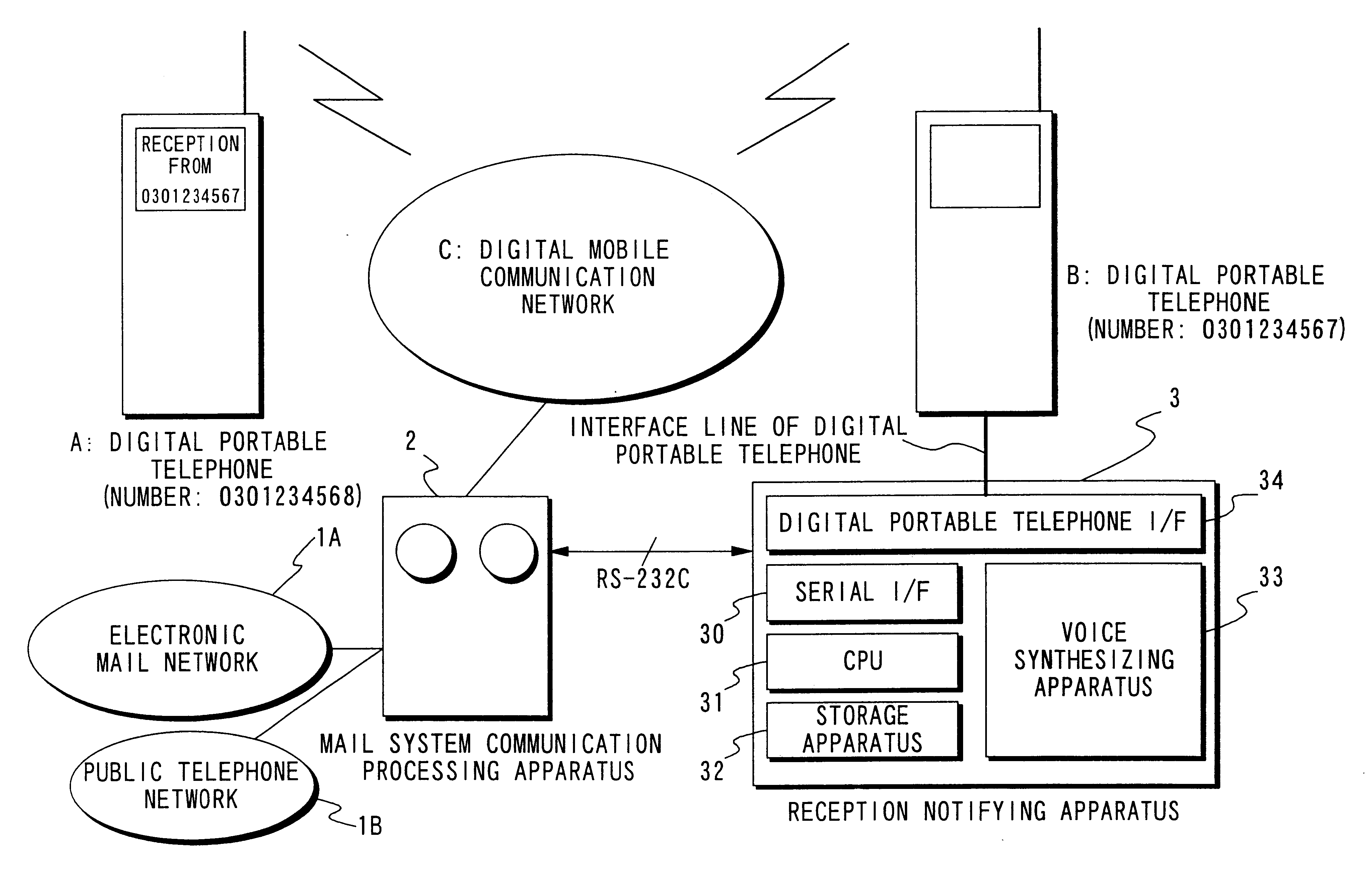
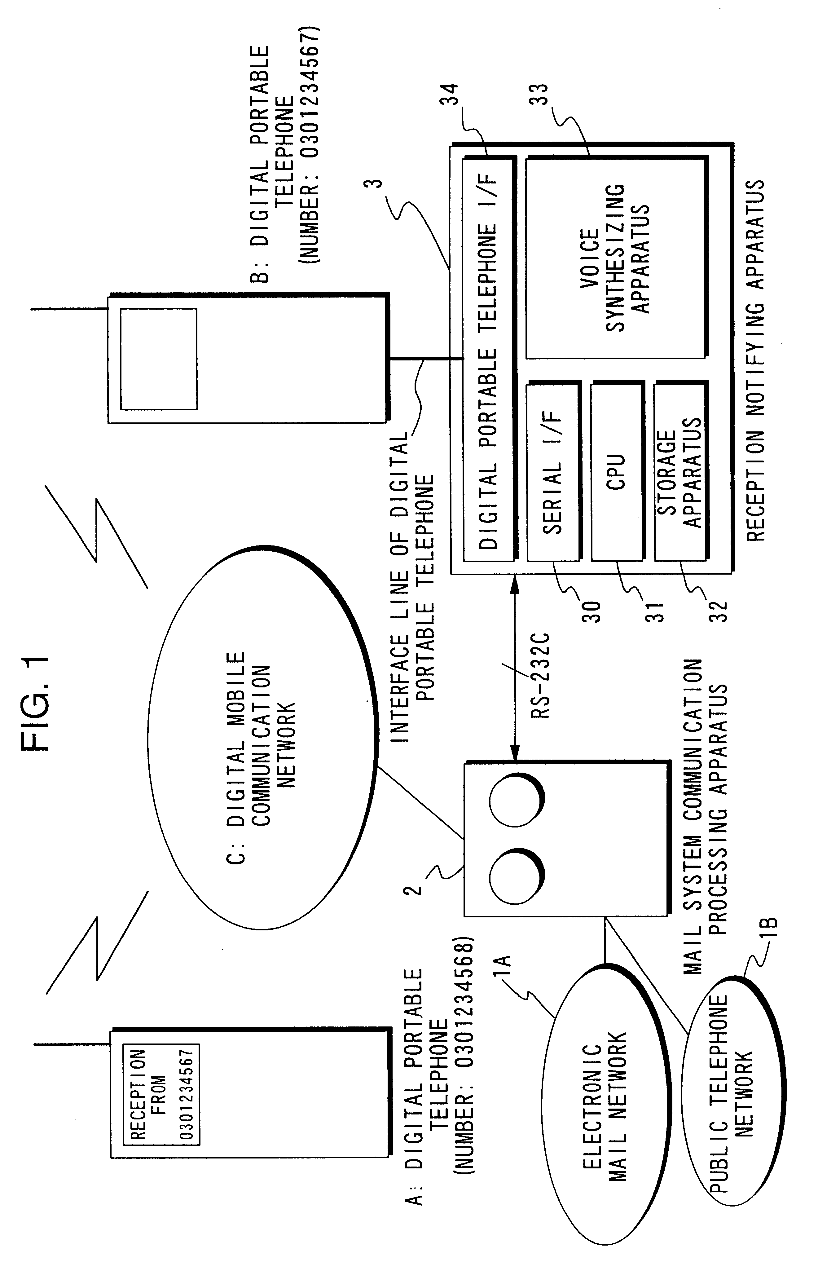
FIG. 1 is a block diagram showing the structure of a mail reception notifying system of an embodiment in this invention. In FIG. 1, A is a digital portable telephone on the user's side, and B is a digital portable telephone on the host side. Digital portable telephones A, B are connected to digital mobile telephone network C. Reception notification of various mails, such as electronic mails, voice mails and facsimile mails, is carried out between digital portable telephones A, B through digital mobile telephone network C. Digital portable devce which display telephones A, B respectively include a display device that displays predetermined characters and symbols.

Digital mobile communication network (communication network) C includes of a switching apparatus which manages transmission information, such as on-line display information, out-of-service-area display information, and the like. The on-line display information indicates whether or not the digital portable telephone of a subsc...


PUM


Abstract

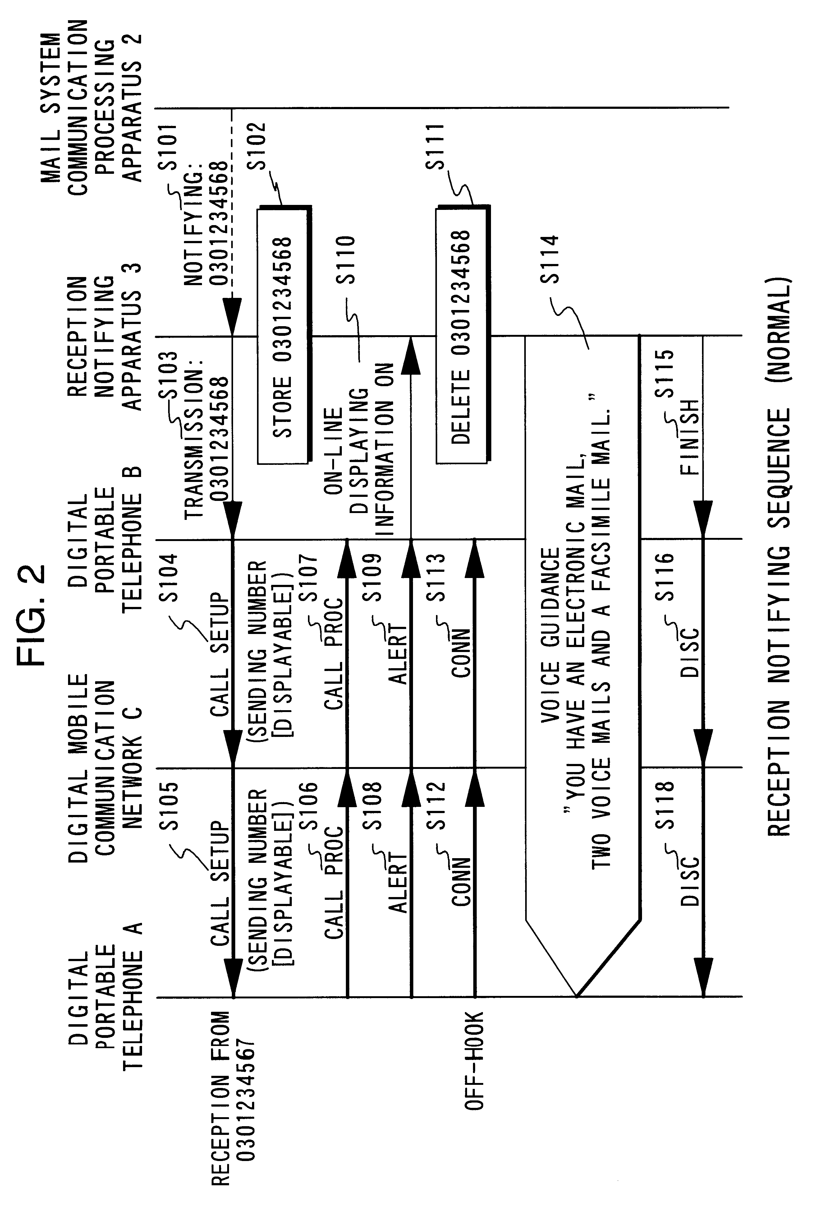
When the telephone number of digital portable telephone A is notified to reception notifying apparatus 3 (S101), the telephone number is stored (S102), and is forwarded to digital portable telephone B (S103). Next, when digital portable telephone B transmits a CALL SETUP signal and a sending number to digital portable telephone A (S104, S105), digital portable telephone A transmits a CALL PROC signal and an ALERT signal to digital portable telephone B (S106-S109). After that, information indicating that the busy line display is ON is forwarded to reception notifying apparatus 3 (S110), and the telephone number is deleted (S111). Furthermore, reception notifying apparatus 3 transmits a voice guidance to digital portable telephone A (S114).

Description

The present invention relates to a mail reception notifying system and a mail reception notifying method which are suitable for providing notification by means of a voice to a user of the receipt of various types of mails, such as electrical mails (E-mails), voice mails and facsimile mails.In the BBS (Britain Board System) system, in which a user uses a personal computer with a modem, for example, the personal computer is connected as a terminal to a host computer through a telephone line, to form a network. Information is then exchanged via electronic mails between users over the network. In this electronic mail service, a file made off-line in advance is transmitted to the host computer along with the ID (identification code) of the user who is to receive the file. The host computer then stores the file after associating it with the ID of the intended recipient. In order to read out the file subsequently, the recipient must access his personal mailbox, and download the file stored...

Claims


Application Information

Patent Timeline
IPC IPC(8): H04M3/50H04M3/537H04Q7/38H04M3/53H04M1/725H04L12/58H04M1/72H04M3/46H04M1/7243H04W4/12
CPCH04L12/587H04L51/24H04M3/5307H04M3/537H04W4/12H04L12/5895H04M1/72547H04M3/46H04M2207/18H04M1/7243H04L51/224H04L51/58
Inventor SAWAI, KOICHI
Owner NTT MOBILE COMM NETWORK INC
Learn More