Fuel injection method of internal combustion engine and fuel injection apparatus of internal combustion engine

a fuel injection method and internal combustion engine technology, applied in the direction of liquid fuel feeders, machines/engines, instruments, etc., can solve the problems of delay in time, inability to inject all the fuel, and inability to achieve the effect of fuel injection

Inactive Publication Date: 2003-07-08
HITACHI LTD +1
View PDF5 Cites 19 Cited by
  • Summary
  • Abstract
  • Description
  • Claims
  • Application Information

AI Technical Summary

Benefits of technology

Another object of the present invention is to provide a fuel injection method of an internal combustion engine and a fuel injection apparatus of an internal combustion engine, in a fuel injection apparatus (a fuel injector) which is performed by a MPI (a multi-point injection) system, so that an atomization degree of a fuel spray injected from a fuel injector can be more heightened (i.e., increased) and the fuel spray into an combustion chamber can be more suitably supplied.
Further, according to the compatibility of the atomization of the fuel spray, an air-fuel mixture having good quality can be generated, and an improvement of the exhaust gas purification and the fuel consumption can be attained.

Problems solved by technology

In the above stated direct injection engine, there is a problem from a manufacturing cost in accordance with many alternations about an engine base, and it has needed to provide a piston head which has a specific shape configuration and requires some surrounding devices.
However, since the kinetic energy of the above stated atomized injection fuel is smaller than the kinetic energy of the injection fuel having the ordinary particle diameters, there is a problem of a delay in time of the injection, fuel in which a penetrating force of the fuel injection is made small and a time is delayed for the injection fuel to reach the cylinder from the fuel injection apparatus (i.e., the fuel injector).
Because of the delay in time of the injection fuel, there is a problem in which all of the injection fuel can not enter in a combustion chamber of the engine during an intake stroke time.
In other words, the delay in time of the injection fuel of the fuel injector to the combustion chamber of the engine is a transportation delay.

Method used


Image

  • Fuel injection method of internal combustion engine and fuel injection apparatus of internal combustion engine
  • Fuel injection method of internal combustion engine and fuel injection apparatus of internal combustion engine
  • Fuel injection method of internal combustion engine and fuel injection apparatus of internal combustion engine

Examples


Embodiment Construction

Hereinafter, a fuel injection method of an internal combustion engine and a fuel injection apparatus of an internal combustion engine of one embodiment according to the present invention will be explained referring to the drawings.

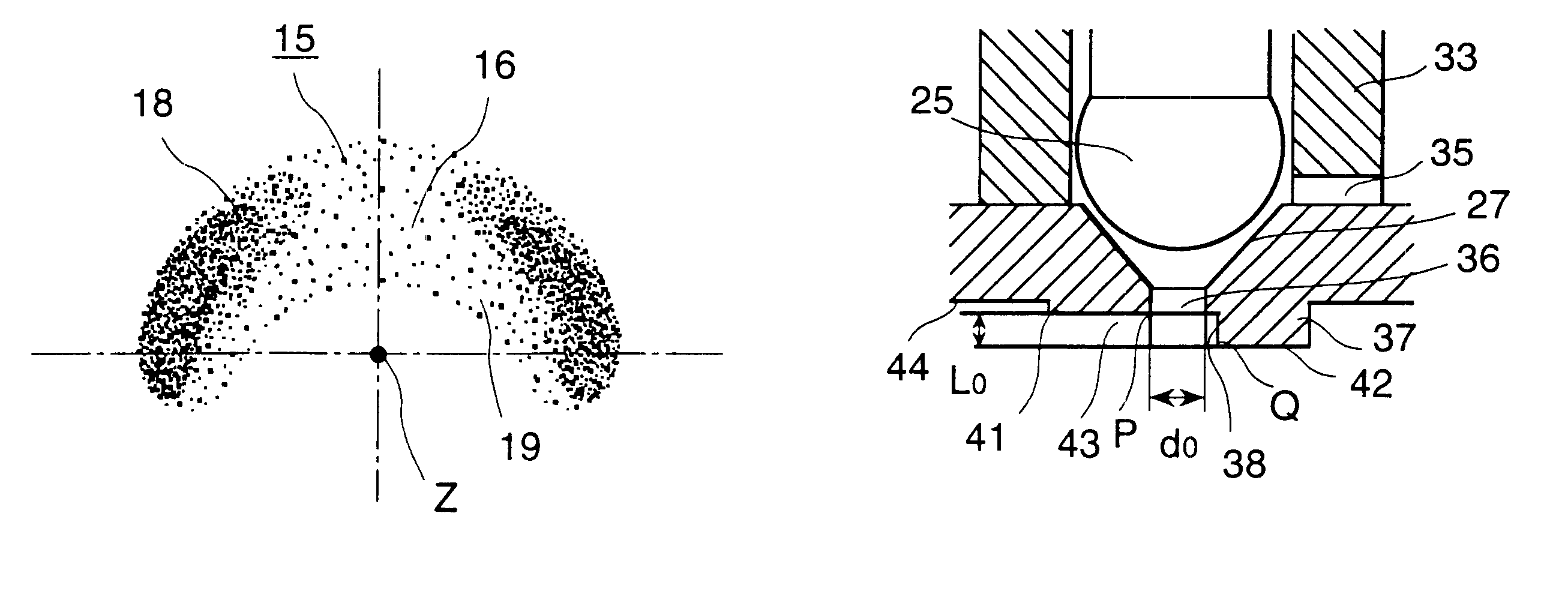
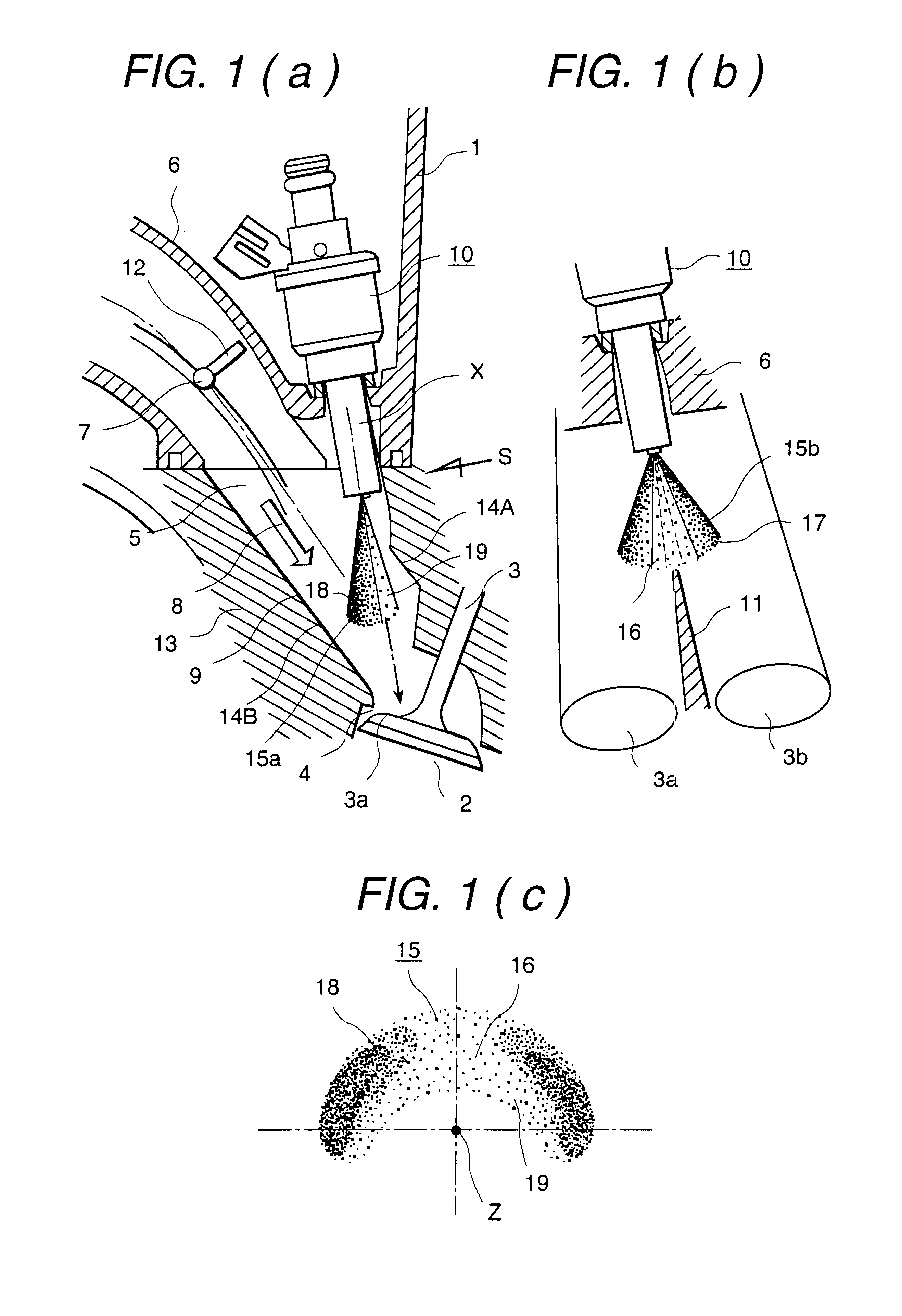
FIG. 1(a) and FIG. 1(b) are views showing a mounting state for mounting to a multi-cylinder internal combustion engine of a fuel injection apparatus (i.e., a fuel injector) of one embodiment according to the present invention. FIG. 1(a) is a partially cross-sectional view of the mounting state of the fuel injector, and FIG. 1(b) is a view which seen from a S direction of FIG. 1(a) and showing a positional relationship between an intake valve and the fuel injector.

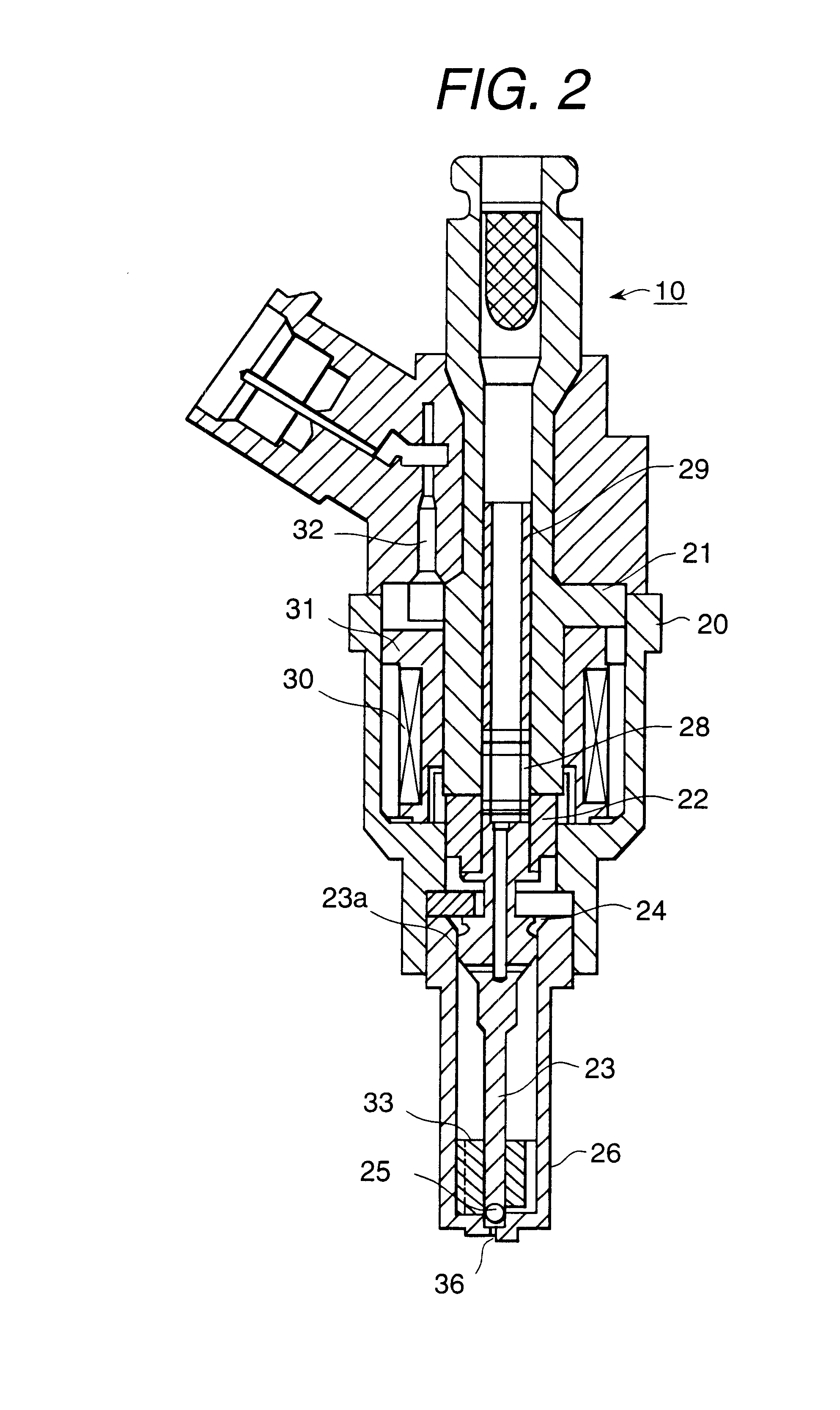
A reference numeral 1 is one of the cylinders of the multi-cylinder internal combustion engine, a reference numeral 2 is a combustion chamber, a reference numeral 3 is an intake valve for opening and closing an intake port 4, a reference numeral 5 is an intake air passage having a central partitio...


PUM


Abstract

In a fuel injection apparatus of an internal combustion engine comprising a fuel injector, an intake valve device for opening and closing an intake port, and an intake air flow control device arranged in an upstream side of the intake valve device, a fuel injection is synchronized with an intake stroke of the engine. A fuel spray is oriented to an inner wall face which is positioned in an opposite side to an inner wall face of a cylinder heads in a fuel injector side and the fuel spray is transported by an air flow having a strong fluidization which is entered from the intake air control device. In a port injection lean burn engine, an adhesion to the wall face according to the fuel spray can be reduced, and a quality and a formation state of an air-fuel mixture in a cylinder can be improved.

Description

1. Technical FieldThe present invention relates to a fuel injection method of an internal combustion engine and in particularly to a fuel injection method of an internal combustion engine in which an atomization of a fuel spray injected from a fuel injector is heightened and the fuel spray is supplied to an intake manifold, and a fuel injection apparatus of an internal combustion engine and in particularly to a fuel injection apparatus of an internal combustion engine in which an atomization of a fuel spray injected from a fuel injector is heightened and the fuel spray is supplied to an intake manifold.2. Prior ArtRecently, from an aspect of an environment protection, exhaust gas regulations and fuel consumption regulations in the automobile field have been enforced exclusively from year to year. As a result of these requirements, improvements in an exhaust gas purification and the fuel consumption of an internal combustion engine and various kinds of internal combustion engines (su...

Claims


Application Information

Patent Timeline
Patent Type & Authority Patents(United States)
IPC IPC(8): F02M61/16F02M61/00F02M61/18F02M61/12F02M69/04F02M65/00F02M51/06
CPCF02M51/0675F02M51/0682F02M61/12F02M61/162F02M61/184F02M61/1853F02M65/00F02M69/044
Inventor OKAMOTO, YOSHIOKADOMUKAI, YUZOMIYAJIMA, AYUMUNAGANO, MASAMISOMENO, TADASHI
Owner HITACHI LTD
Why Eureka
Try Eureka