Patellar alignment device

a technology for patellar and spondylose veins, applied in the field of patellar alignment devices, can solve the problems of patella prosthesis movement, patella prosthesis movement, and inability to accurately locate the proper position, etc., and achieve the effect of accurate positioning the proper position

Inactive Publication Date: 2003-07-08
HUGHES JOE L
View PDF3 Cites 107 Cited by
  • Summary
  • Abstract
  • Description
  • Claims
  • Application Information

AI Technical Summary

Benefits of technology

The present invention is a self-aligning patella trial device which allows the surgeon to accurately locate the proper position for the final patella prosthesis. The present patella trial device further eliminates the need to perform additional surgical procedures to allow proper tracking of the device. The trial device of the present invention comprises two components. One of the components is a baseplate for attaching to the posterior portion of the patella. The baseplate is a flat circular plate having a series of slots, preferably radially oriented, in the plate, which may or may not be used during the trial procedure. One side of the flat plate contains small spikes for temporary attachment to the posterior portion of the patella.

Problems solved by technology

However, there are some patella prosthesis designs that either require more than one hole or require a recessed area for acceptance of the final component.
Therefore, if the surgeon drills the hole for mounting the trial patella prosthesis in the drilled proposed location on the back of the patella, then the patella prosthesis will not track properly and additional surgical procedures are necessary to cause the patella to track properly.
In others the patella prosthesis may be so poorly aligned that it may move completely out of the groove or dislocate.
Additionally, a misaligned patella may cause excessive wear on the prosthetic components of the knee joint, which may reduce the life of the knee joint and necessitate additional surgery.
Many post-operative complications in total knee arthroplasties have been attributed to poor patellar tracking.
Dislocations, subluxations, excessive polyethylene wear and particulate debris are some of these complications.
However, a lateral release may be problematic itself since it is believed to reduce the circulation to the patella and could encourage fractures, aseptic necrosis, and / or loosening of the patella component.
Also, post-operative rehabilitation is much more difficult as there is more bleeding and scarring post-operatively.
Existing devices and methods for placement of the prosthesis do not consistently allow for propel placement of the final patella prosthesis.

Method used


Image

  • Patellar alignment device
  • Patellar alignment device
  • Patellar alignment device

Examples


Embodiment Construction

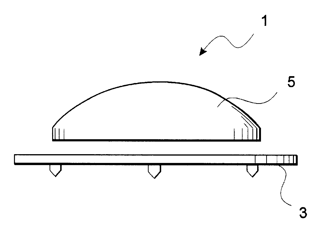
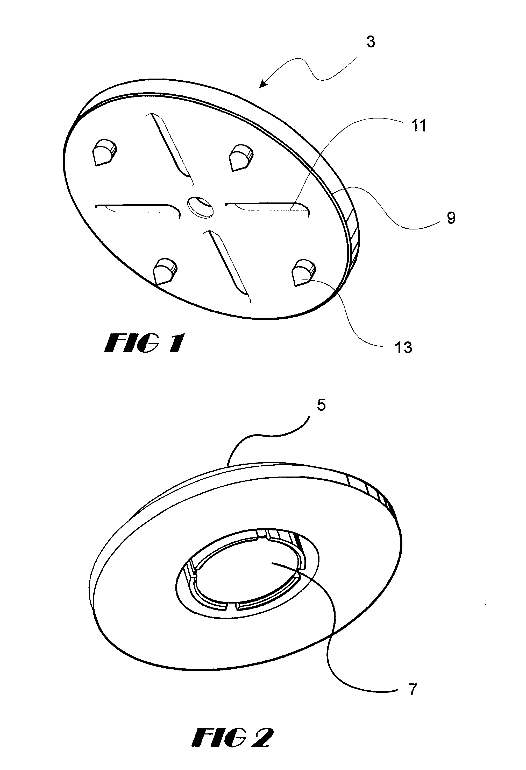
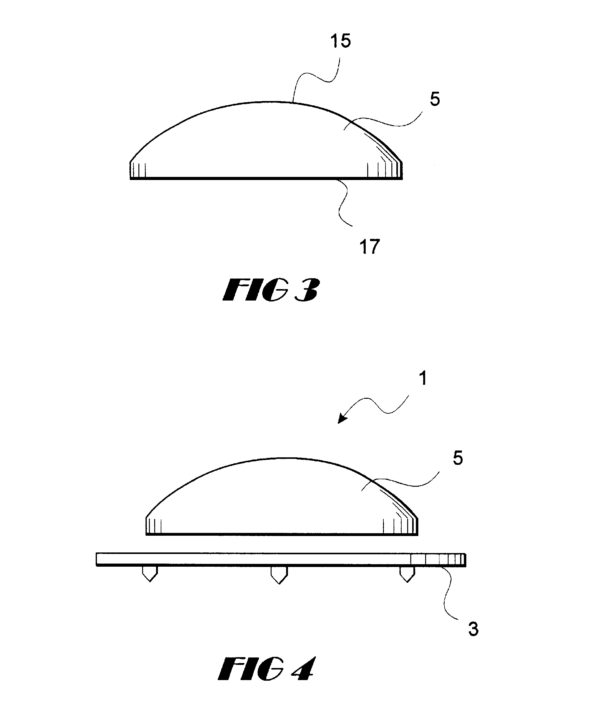
Referring now to FIGS. 1-4, a preferred embodiment of the present patellar alignment device 1 is shown. As indicated in the drawings, the self-aligning patella trial device 1 of the present invention comprises a baseplate 3 for attaching to the posterior portion of a patella (not shown) and a mobile component 5 which is removably attached to the baseplate 3 preferably by magnets 7.

The baseplate 3 preferably is a flat circular plate 9 having slots 11, preferably radially oriented, in the baseplate 3. The slots 11 allow a surgeon to mark the patella during the knee surgery for proper placement of the final prosthetic device. One side of the flat plate 9 contains small spikes 13 for temporary attachment to the posterior portion of the patella. As shown in FIG. 5, outside prongs 14 may be used for added support and positioning of the baseplate 3. However, any suitable means may be used for attaching the baseplate 3 to the patella for purposes of performing the trial, such as screws, spr...


PUM


Abstract

A patellar alignment device for determining the position of a patella prosthesis. The device comprises two components-a baseplate and a mobile component which is preferably magnetically attached to the baseplate. During a surgical procedure to replace the knee, the baseplate is temporarily attached to the back of the patella. The baseplate may contain spikes or prongs to secure it to the patella. The baseplate further includes a series of slots for marking the patella. The mobile component resembles a patella and is placed on the baseplate. The patella with the alignment device in place is then placed in position on the knee and trialed. Because the mobile component is free to move on the baseplate, it finds the position that is most amenable to a natural knee movement. The alignment device is then exposed and the patella is marked at the position of the mobile component. Since the baseplate contains a series of slots, the patella can be easily marked at several locations around the mobile component. The entire patella alignment assembly is then removed and the final prosthetic device can be inserted at the marked location.

Description

1. BACKGROUNDFor a variety of reasons, whether from the natural aging process or from an injury, the knee may become damaged to such an extent that it needs to be completely repaired--usually through a surgical procedure called a total knee arthroplasty. In an arthroplasty, the damaged portions of the knee are removed and replaced with prosthetic components that are the size and shape of the original undamaged portions of the knee. It is important that the replacement prosthetics be aligned properly to prevent unnecessary wear and tear on the new components and to prevent complications from occurring due to the misalignment. To assist with the proper alignment of the prosthetic replacements, trial components are first installed during surgery. The trial components are the size and shape of the final components but are only used to test the alignment and fit of the knee before installing the permanent components.There are three primary bones that comprise a knee joint in a human that...

Claims


Application Information

Patent Timeline
Patent Type & Authority Patents(United States)
IPC IPC(8): A61B17/14A61B17/15A61F2/46A61F2/30A61B19/00A61F2/00A61F2/38
CPCA61B17/158A61F2/4657A61F2/4684A61B2019/5404A61F2002/30079A61F2002/30604A61F2002/3881A61F2002/4661A61F2002/4681A61F2210/009A61B2090/3904
Inventor HUGHES, JOE L.
Owner HUGHES JOE L
Why Eureka
Try Eureka