Multi-eye image sensing apparatus

a multi-eye, image sensing technology, applied in the direction of instruments, optical elements, panoramic photography, etc., can solve the problems of insufficient stereoscopic sense, large apparatus, and lens interference of respective image sensing optical systems, so as to reduce the number of building components and compact arrangement

Inactive Publication Date: 2003-07-08
CANON KK
View PDF12 Cites 6 Cited by
  • Summary
  • Abstract
  • Description
  • Claims
  • Application Information

AI Technical Summary

Benefits of technology

It is the first object of the present invention to provide a multi-eye image sensing apparatus, which can reduce the number of building components of image sensing optical systems, and can realize a compact arrangement.

Problems solved by technology

When the distance between the two, right and left image sensing systems is short, the right and left images have no disparity with respect to a far object, and sufficient stereoscopic sense cannot be obtained.
However, in the above-mentioned conventional multi-eye image sensing apparatus, since the convergence angle and base length of its image sensing optical systems are changed by moving and rotating these optical systems, the entire apparatus becomes bulky if the image sensing optical systems are comprised of coaxial optical systems.
However, since the entrance pupil position cannot be largely moved toward the object side, when the convergence angle becomes equal to or larger than a predetermined angle, lenses in the respective image sensing optical systems may interfere with each other.
However, in the conventional apparatus, since a plurality of lenses are built in lens barrels in the right and left image sensing systems, the optical characteristics of the right and left image sensing systems suffer variations.
However, when the trapezoidal distortion is removed by only the image process, the image quality deteriorates.

Method used


Image

  • Multi-eye image sensing apparatus
  • Multi-eye image sensing apparatus
  • Multi-eye image sensing apparatus

Examples


first embodiment

[First Embodiment]

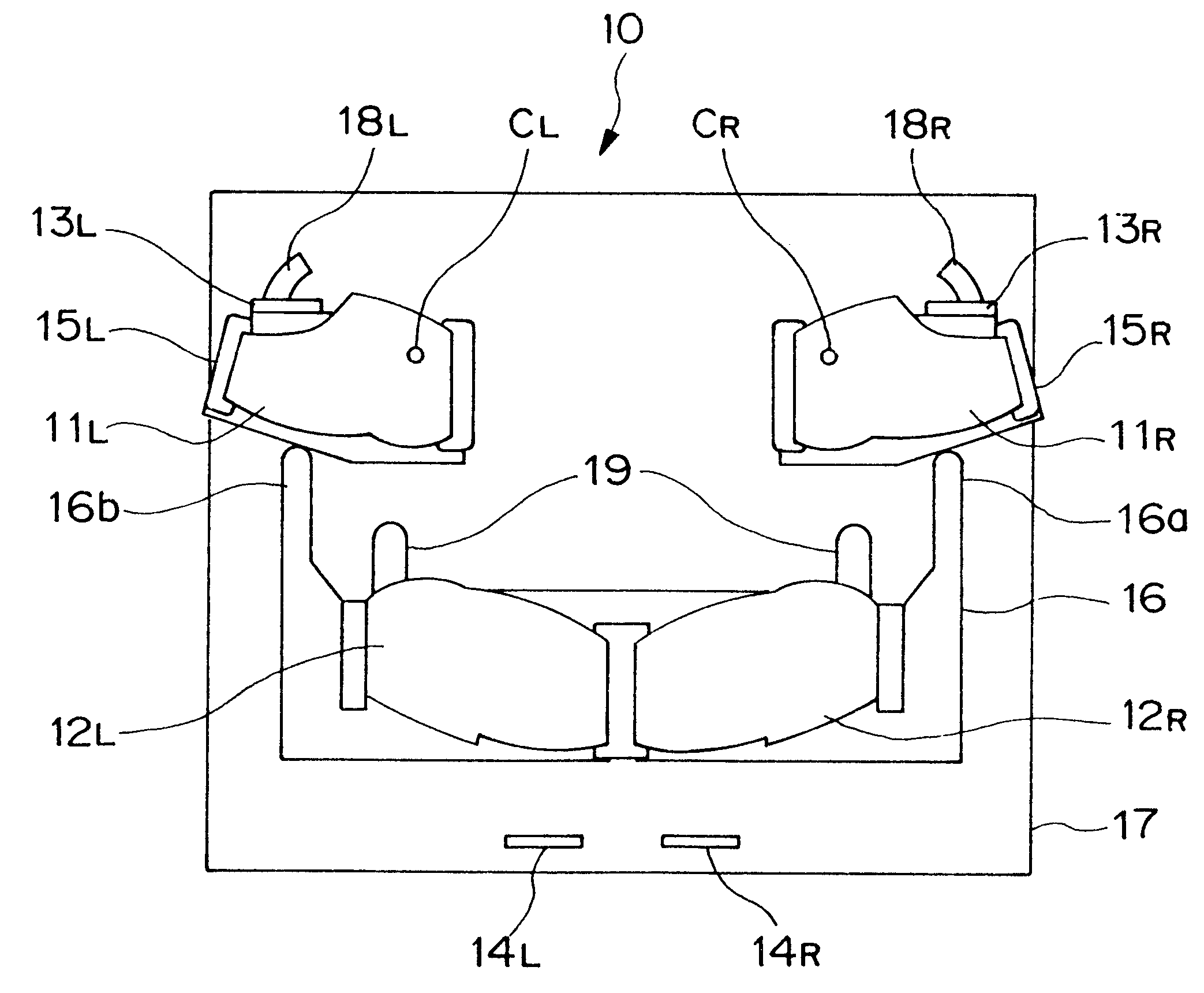
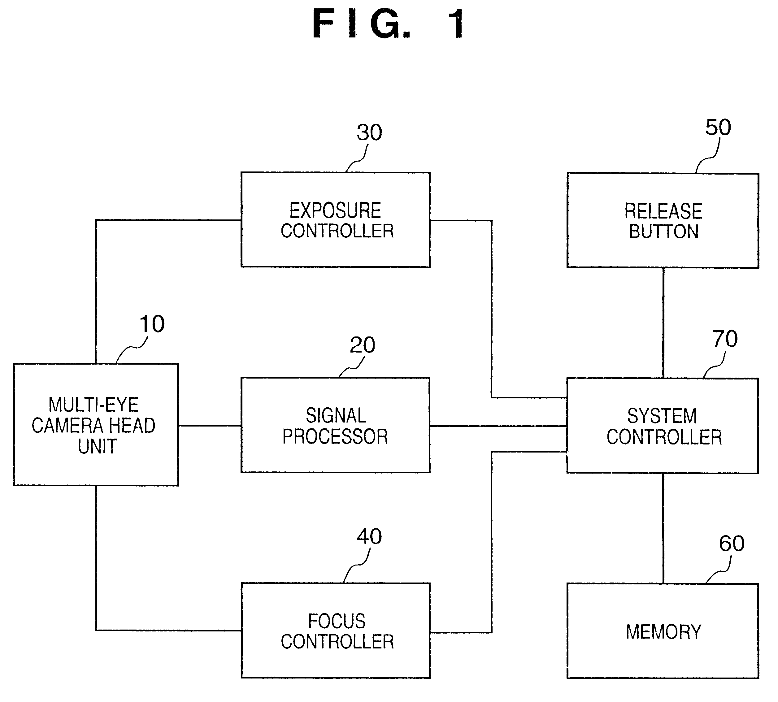
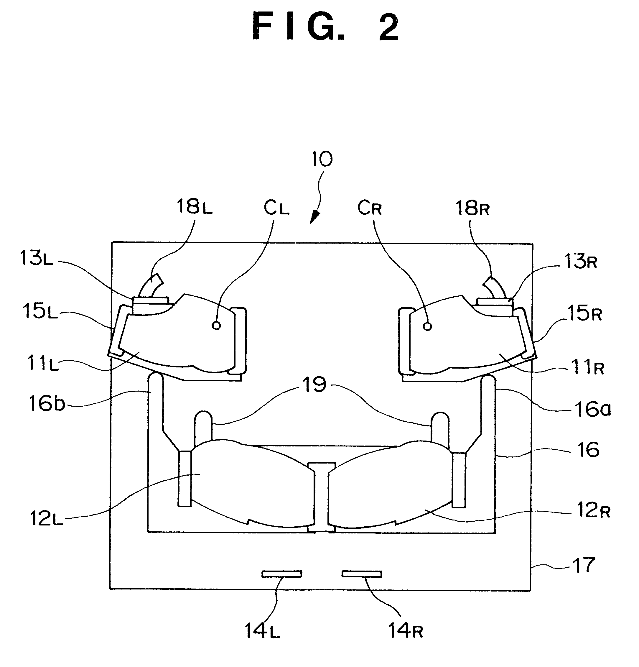
FIG. 1 is a block diagram showing the arrangement of a multi-eye image sensing apparatus of the first embodiment.

Referring to FIG. 1, reference numeral 10 denotes a multi-eye camera head unit, which senses images of an object, and outputs image signals. Reference numeral 20 denotes a signal processor for converting image signals obtained by the multi-eye camera head unit 10 into image data of, e.g., JPEG (Joint Photographer Expert Group) or the like. Reference numeral 30 denotes an exposure controller for controlling the exposure values of right and left image sensing systems of the multi-eye image camera head unit 10 in correspondence with the brightness of the object.

Reference numeral 40 denotes a focus controller for controlling focusing on the object. Reference numeral 50 denotes a release button. Reference numeral 60 denotes a memory for storing image data. Reference numeral 70 denotes a system controller for controlling the operation of the overall multi-eye ...

second embodiment

[Second Embodiment]

FIG. 7 is a block diagram showing the arrangement of a multi-eye image sensing apparatus of the second embodiment.

Referring to FIG. 7, reference numeral 10A denotes a multi-eye camera head unit which senses images of an object, and outputs image signals.

Reference numeral 20 denotes a signal processor for converting image signals obtained by the multi-eye camera head unit 10A into image data of, e.g., JPEG or the like. Reference numeral 30 denotes an exposure controller for controlling the exposure values of right and left image sensing systems of the multi-eye image camera head unit 10A in correspondence with the brightness of the object. Reference numeral 40 denotes a focus controller for controlling focusing on the object.

Reference numeral 50 denotes a release button. Reference numeral 60 denotes a memory for storing image data. Reference numeral 70 denotes a system controller for controlling the operation of the overall multi-eye image sensing apparatus. Refere...

second embodiments

The first and second embodiments provide multi-eye image sensing apparatuses which can respectively change the convergence angle and base length. However, these functions may be combined to construct a multi-eye image sensing apparatus which can change both the convergence angle and base length.

The image sensing systems that use offaxial optical system blocks as the optical elements 11R, 11L, 12R, and 12L have been exemplified. Since high degree of freedom in layout of the entrance and exit reference axes is realized when offaxial optical system blocks are included, some of the optical elements 11R, 11L, 12R, and 12L may be replaced by conventional coaxial optical system blocks.

In this manner, since each of the right and left image sensing systems includes at least one prism as an offaxial optical system block, which includes an offaxial reflecting surface that is an asymmetric aspherical surface as a building component, and has a refractive power that can form a real image as a who...


PUM


Abstract

In a multi-eye camera head unit (10), a panoramic image sensing exchangeable camera head unit (111) and three-dimensional image sensing exchangeable camera head unit (112) are exchanged in correspondence with the image sensing mode. The panoramic image sensing exchangeable camera head unit (111) includes a pair of optical elements (111R, 111L), which comprise offaxial optical systems each having a plurality of reflecting and refracting surfaces. The three-dimensional image sensing camera head unit (112) includes a pair of optical elements (112R, 112L), which comprise offaxial optical systems each having a plurality of reflecting and refracting surfaces.

Description

BACKGROUND OF THE INVENTION1. Field of the InventionThe present invention relates to a multi-eye image sensing apparatus having a plurality of image sensing systems.2. Description of Related ArtConventionally, as a method of sensing a three-dimensional image of an object, a method using a multi-eye image sensing apparatus having a plurality of image sensing optical systems is known. In this image sensing method, an object is sensed using a plurality of image sensing systems, e.g., two, right and left image sensing systems, and the three-dimensional shape of the object is recognized by disparity produced between the right and left image portions of the object sensed by the right and left image sensing systems. Such three-dimensional shape recognition works in basically the same way a person recognizes the shape of an object as a three-dimensional shape due to disparity produced upon capturing the object by the right and left eyes.In image sensing using the multi-eye image sensing app...

Claims


Application Information

Patent Timeline
Patent Type & Authority Patents(United States)
IPC IPC(8): G02B13/06G03B35/10G02B17/08G03B35/00G02B27/22G03B37/00G03B37/04H04N13/00H04N13/239H04N13/243
CPCG02B13/06G02B17/0848G02B17/086G02B27/2242G03B35/10G03B37/04G06T7/0022H04N13/0239H04N13/0296H04N13/0003H04N13/0055H04N13/0242H04N2013/0081H04N2013/0088H04N2013/0096H04N19/597H04N13/0289G06T7/97H04N13/289H04N13/243H04N13/189H04N13/296H04N13/10H04N13/239G02B30/36
Inventor YANO, KOTAROARAKI, KEISUKESUNAGA, TOSHIHIRO
Owner CANON KK
Why Eureka
Try Eureka