
Method and system for run-time logic verification of operations in digital systems

a digital system and logic verification technology, applied in the field of electronic digital systems, can solve the problems of increasing the complexity and physical density of the system, increasing the functional complexity of the modern digital system, and inherently difficult to verify the system before construction and/or validation

Inactive Publication Date: 2003-07-08
IBM CORP
View PDF18 Cites 68 Cited by
  • Summary
  • Abstract
  • Description
  • Claims
  • Application Information

AI Technical Summary

Problems solved by technology

The evolution of digital systems and circuit technology has led to systems of ever increasing complexity and physical density.
This relentless pace of innovation has led to systems that are inherently difficult to verify before construction and / or validated by testing after construction.
The increased functional complexity of modern digital system leads to systems with extremely complicated functional behavior and large numbers of functional units.
Such portions of a digital system are typically difficult to verify during simulation and require intensive directed effort and manual testing in order to verify these functions.
Often, simulation fails to adequately verify such infrequently-utilized functions which constitute the source of many design errors in modern digital systems.
In addition, modern simulation techniques are several orders of magnitude slower than actual system operation.
Further, increased circuit density results in structures, such as data arrays, that are more susceptible to errors induced by environmental sources such as naturally occurring alpha particles.
However, due to the fact that these mechanisms are rarely exercised and often uncontrollably exercised (i.e. the error is caused by a natural environmental process that is not directly controllable), it is difficult to validate, through laboratory testing, these error correction mechanisms.
Simulation, however, is typically several orders of magnitude slower than actual system operation.

Method used


Image

  • Method and system for run-time logic verification of operations in digital systems
  • Method and system for run-time logic verification of operations in digital systems
  • Method and system for run-time logic verification of operations in digital systems

Examples


Embodiment Construction

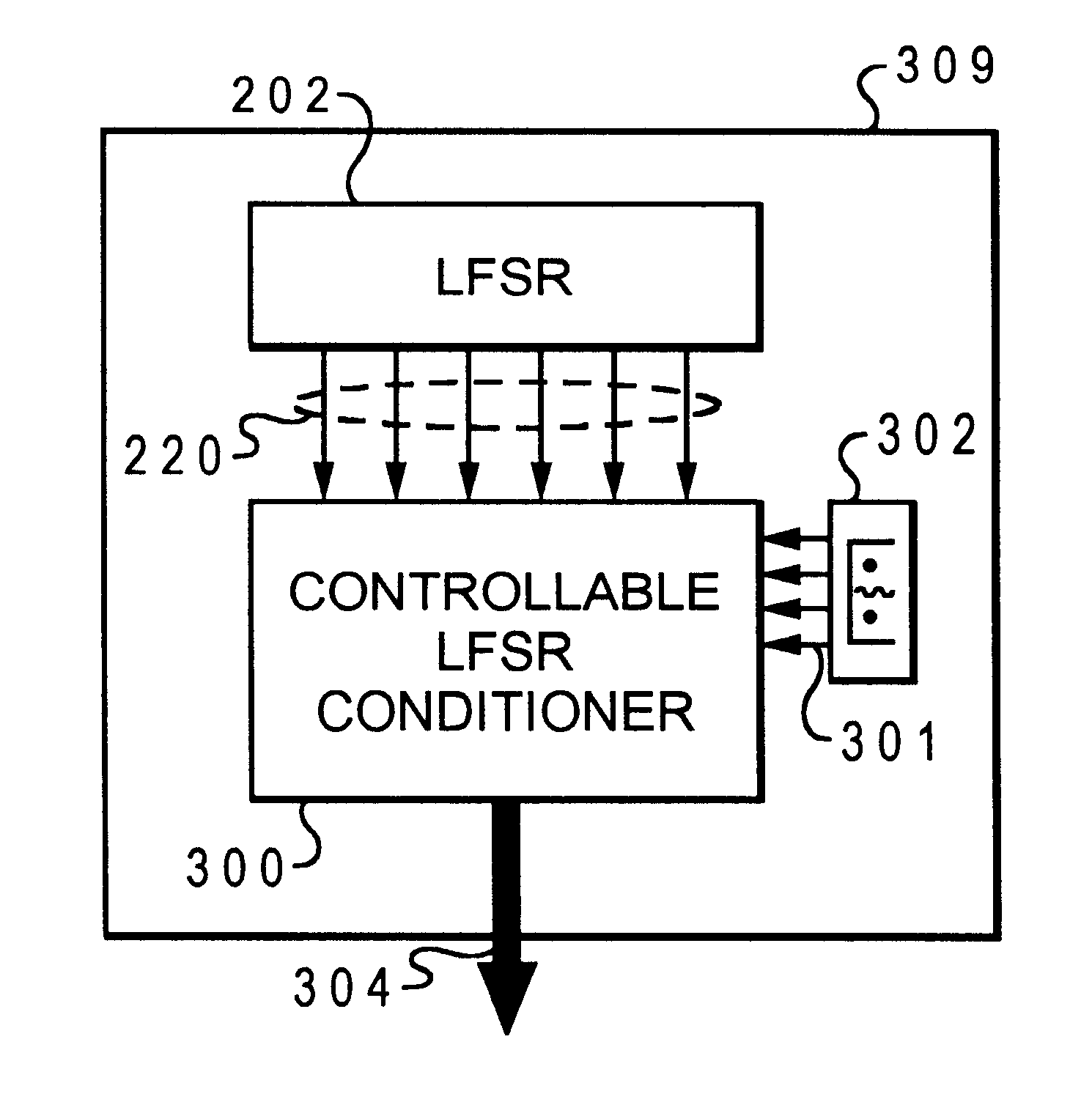
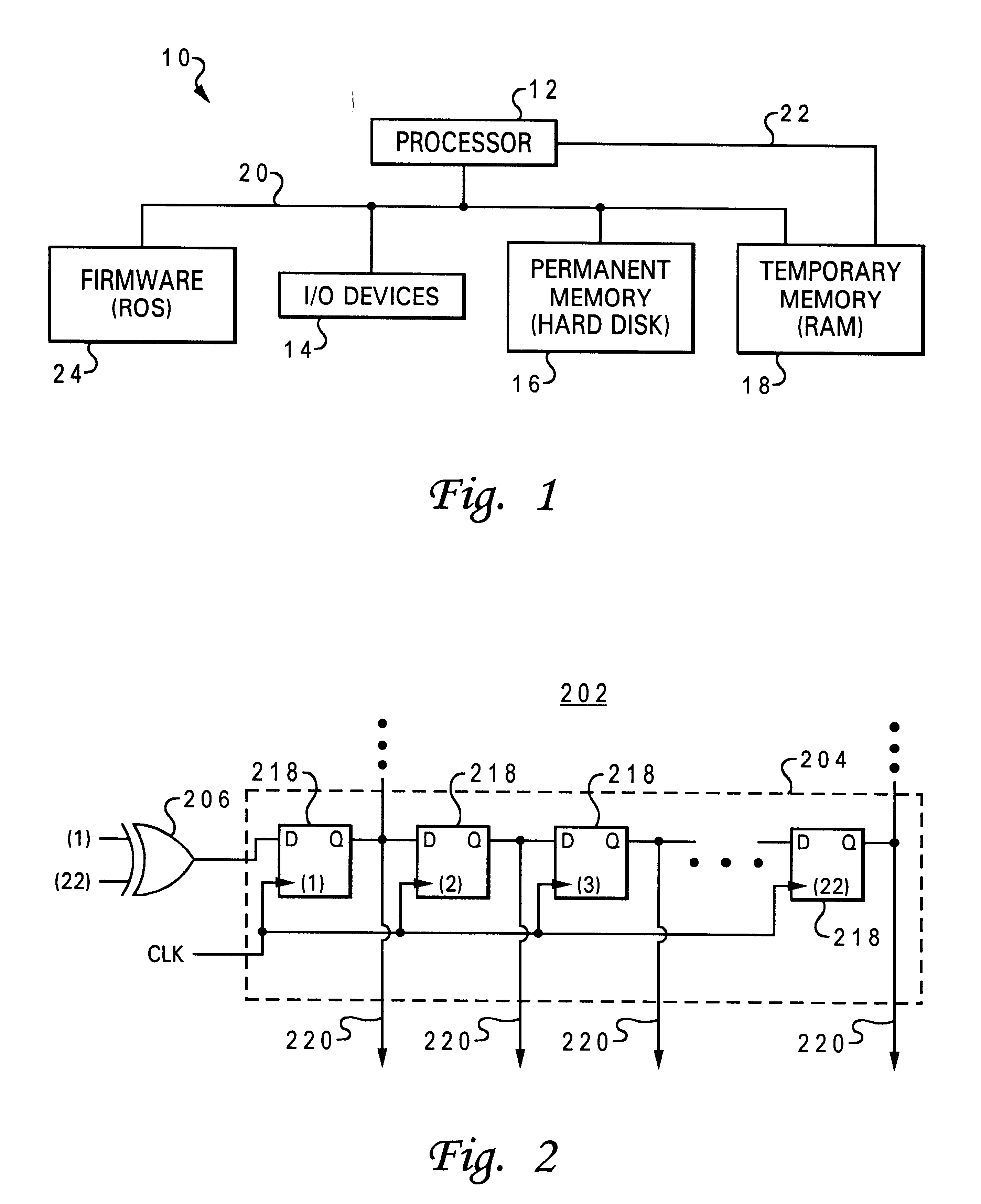
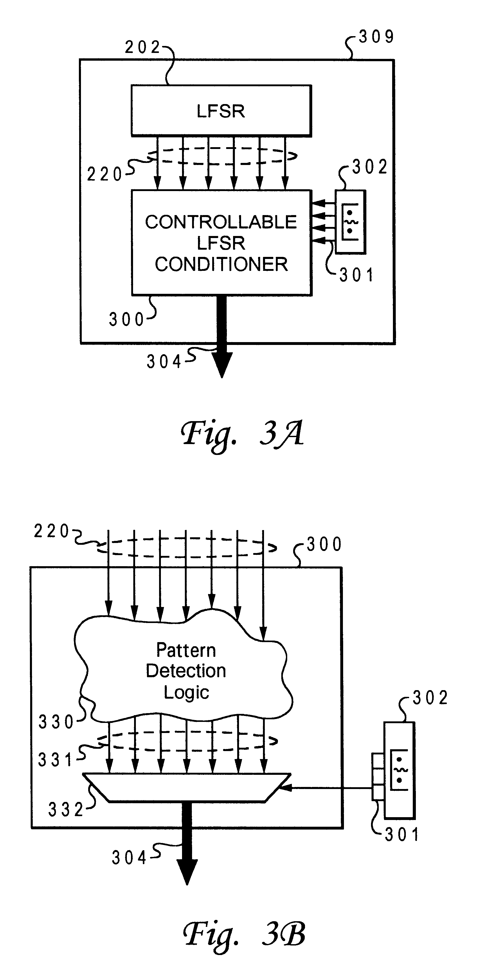
With reference now to the figures, and in particular with reference to FIG. 1, there is illustrated a high level block diagram of a multiprocessor data processing system 10 in accordance with the present invention. Data processing system 10 is one embodiment of a digital system referenced throughout the invention. Those skilled in the art will appreciate that other types of digital systems are applicable to the invention. The heart of data processing system 10 is a central processing unit (CPU) or processor 12 which is connected to several peripheral devices, including input / output (I / O) devices 14 (such as a display monitor and keyboard) for the user interface, a permanent memory device 16 (such as a hard disk or floppy diskette) for storing the data processing system's operating system and user programs, and a temporary memory device 18 (such as dynamic random-access memory or DRAM) that is utilized by processor 12 to carry out program instructions. Processor 12 communicates with ...


PUM


Abstract

A system for controllable run-time verification of operations in a logic structure of a digital system. The system comprises a controllable bit stream generator which produces a controlled bit stream output. The controlled bit stream output corresponds to a bit sequence which instantiates a verification of operations within the logic structure. The system also comprises means for coupling the controlled bit stream output to the logic structure to verify the operations of the logic structure.

Description

1. Technical FieldThe present invention generally relates to electronic digital systems, and in particular to a method and apparatus for generating a bit stream for utilization in an electronic digital system. Still more particularly, the present invention relates to a method and apparatus for generating a controllable bit stream for utilization in logic verification of operations within an electronic digital system.2. Description of the Related ArtThe evolution of digital systems and circuit technology has led to systems of ever increasing complexity and physical density. This relentless pace of innovation has led to systems that are inherently difficult to verify before construction and / or validated by testing after construction.The increased functional complexity of modern digital system leads to systems with extremely complicated functional behavior and large numbers of functional units. Within these numerous units, there are often paths and functions within the system that are ...

Claims


Application Information

Patent Timeline
IPC IPC(8): H04B17/00G01R31/3181G01R31/3185
CPCG01R31/31813G01R31/318547G01R31/318566
Inventor WILLIAMS, DEREK EDWARD
Owner IBM CORP
Learn More