Device and method for plugging a bone channel with an expandable medullary plug

a bone channel and expandable technology, applied in the field of medical devices, can solve the problems of limited flexibility, complicated manufacturing of inflatable bone plugs, and use of internal valves associated with needles for injecting fluid,

Inactive Publication Date: 2003-07-15
HAJIANPOUR MOHAMMED ALI
View PDF23 Cites 27 Cited by
  • Summary
  • Abstract
  • Description
  • Claims
  • Application Information

AI Technical Summary

Benefits of technology

It is a third objective of the present invention to provide a medullary bone channel which expands to provide stable attachment to surfaces within a bone channel.

Problems solved by technology

However, this type of bone cement plug, having a finite number, such as two, mechanically coupled legs to expand and structures shaped as partial disks for contacting the bone channel, is limited in its flexibility in terms of an ability to compensate for differences in the diameter of various bone channels into which the plug may be inserted.
Such materials, which have elastic properties allowing substantial elongation, are subject to cutting and puncturing due to bone splinters and sharp edges in a channel cut into bone, as the plug is moved into position within the channel.
Furthermore, the use of an internal valve associated with a needle for injecting a fluid complicates the manufacture of the inflatable bone plug.
Also, the separate formation of a bone plug from cement and subsequent removal of the conduit and inflatable body to allow insertion of the prosthesis may lengthen the time required for a hip replacement procedure.
However, the expansion of the cement restrictor is limited to the transition between the first stable state and the second stable state, together with elastic and plastic deformation of the material.
This method thus does not offer the kind of flexibility of a system with an inflatable body in expansion to meet varying conditions within the bone channel.
Furthermore, the time required to apply liquids at different temperatures to make the transitionable body perform as desired may increase the time required for hip replacement surgery.

Method used


Image

  • Device and method for plugging a bone channel with an expandable medullary plug
  • Device and method for plugging a bone channel with an expandable medullary plug
  • Device and method for plugging a bone channel with an expandable medullary plug

Examples


Embodiment Construction

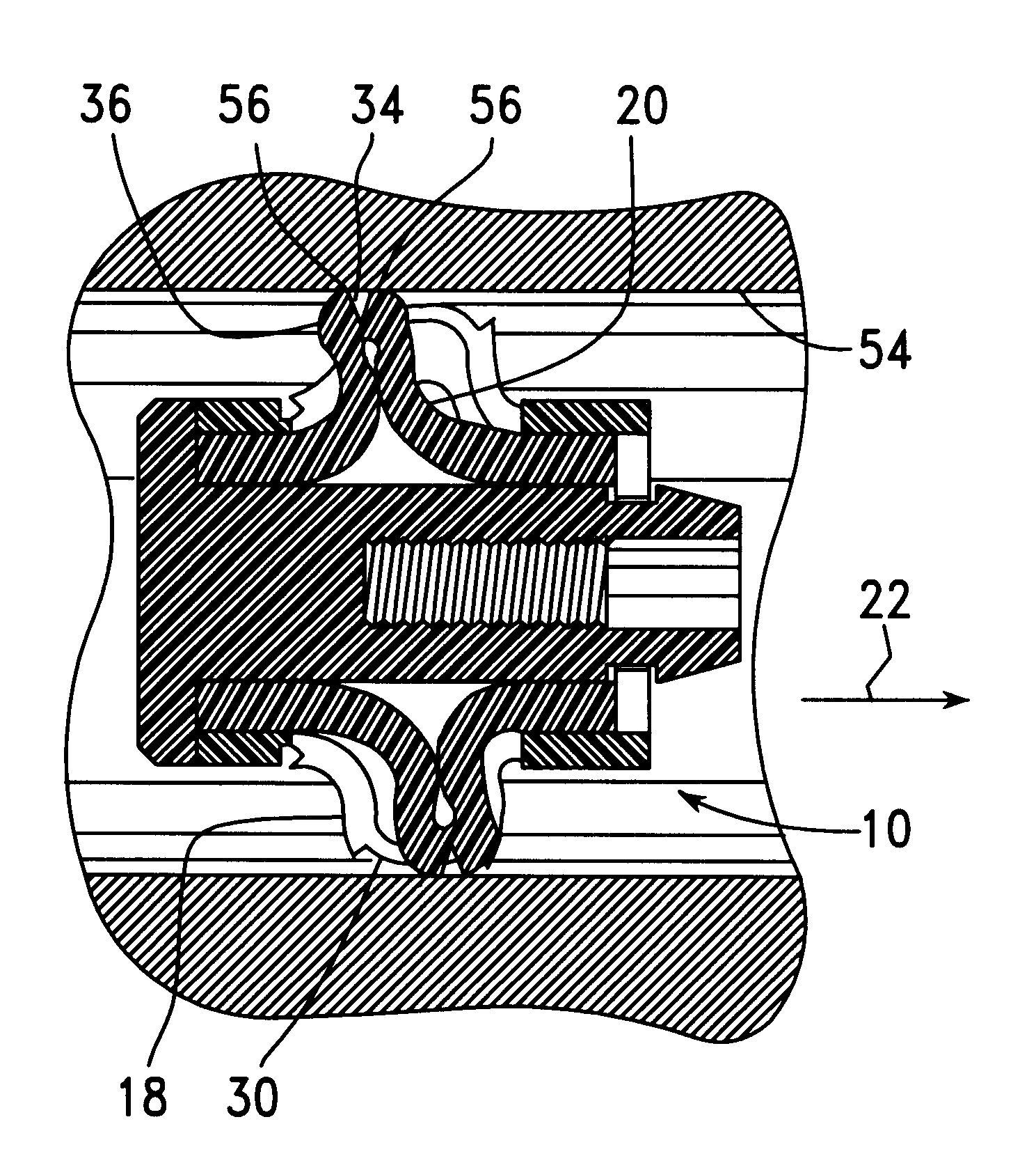
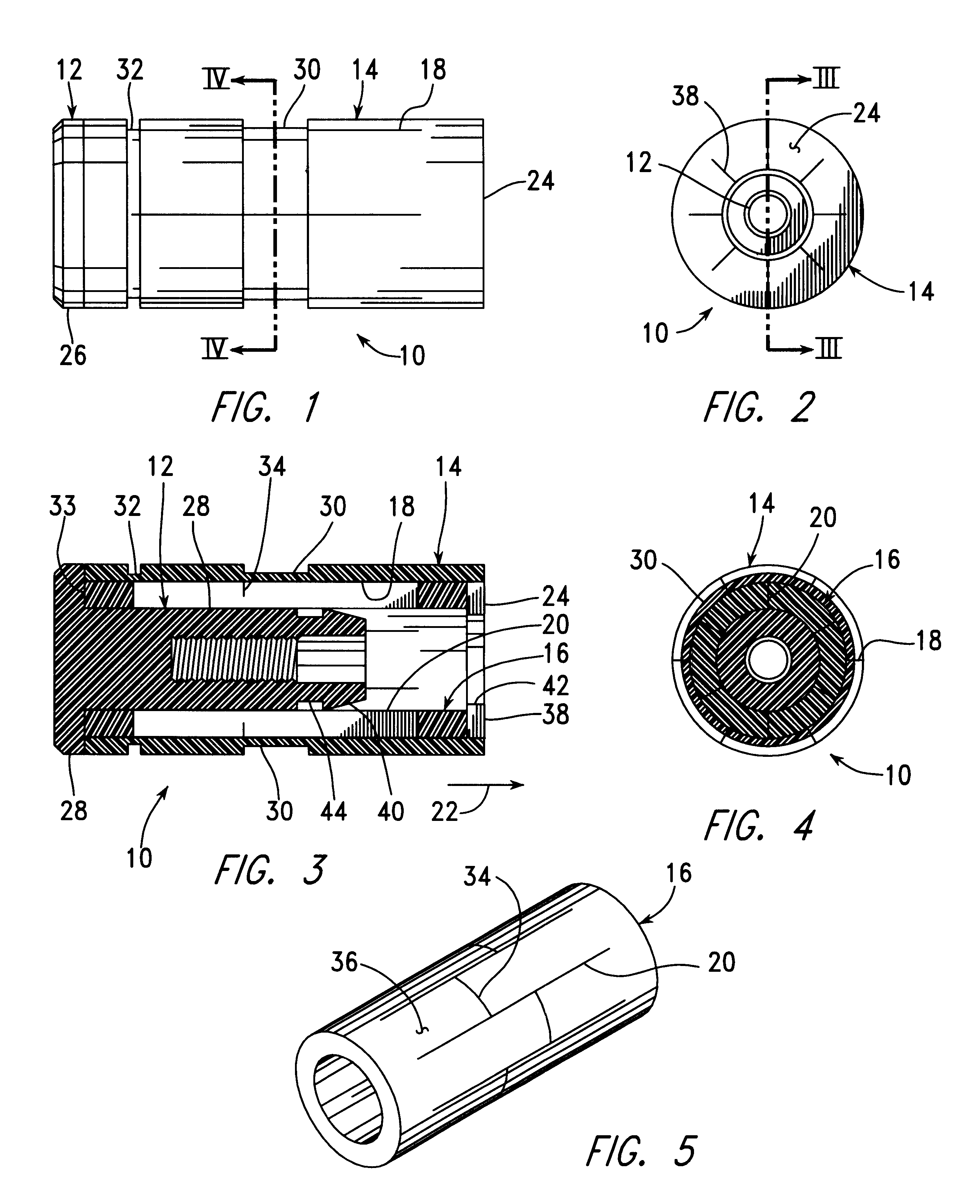
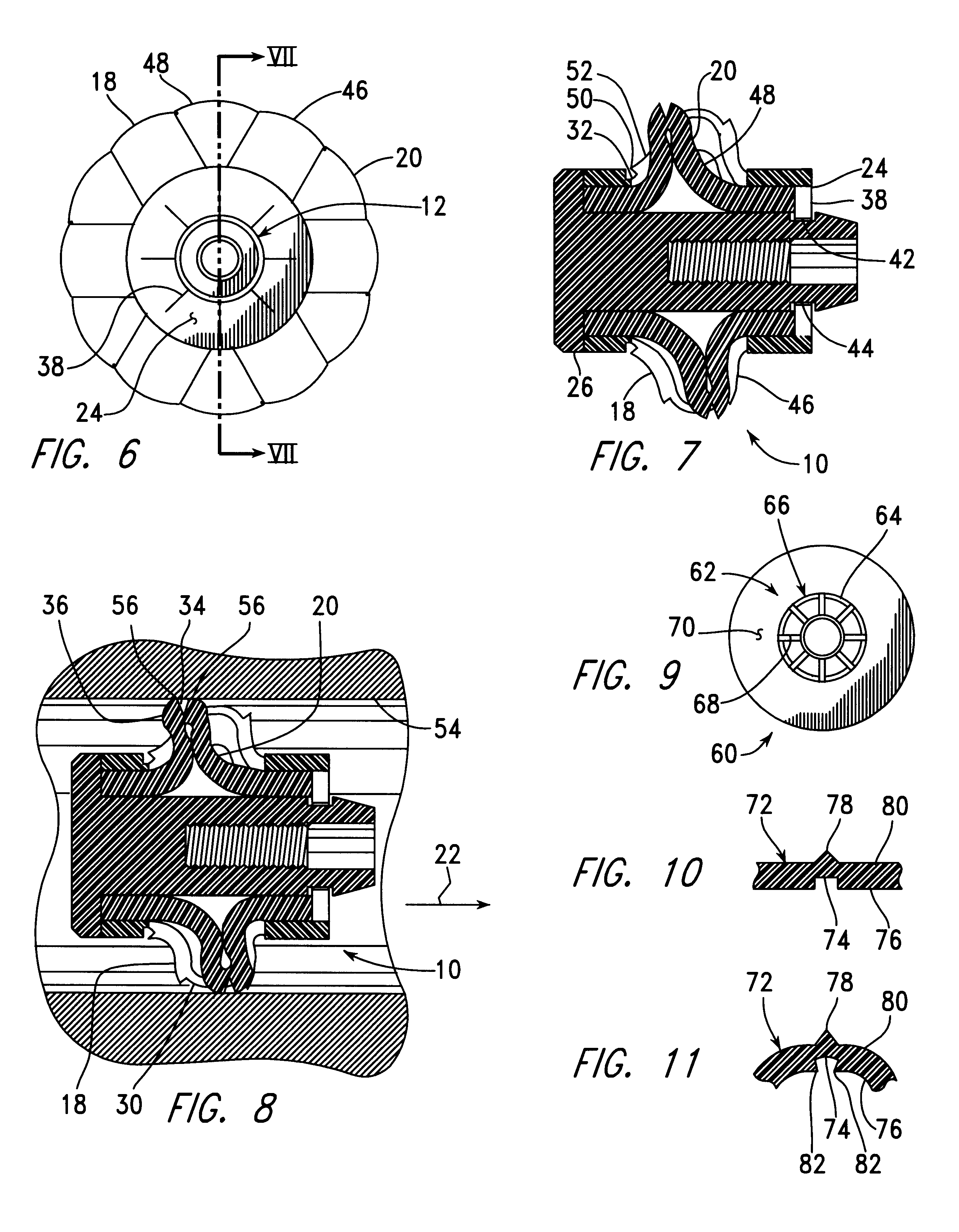
FIGS. 1-4 show an expandable medullary bone plug, generally indicated as 10, built in accordance with the present invention, in its initial, unexpanded condition, with FIG. 1 being a side elevation thereof, with FIG. 2 being a proximal end view thereof, with FIG. 3 being a longitudinal cross-sectional view thereof, taken as indicated by section lines III--III in FIG. 2, and with FIG. 4 being a transverse cross-sectional view thereof, taken as indicated by section lines IV--IV in FIG. 1.

The medullary bone plug 10 includes an actuator 12, an outer sleeve 14, and an inner sleeve 16 extending within the outer sleeve 14. The central portion of the outer sleeve 14 is divided into six outer flexible beams 18, while the central portion of the inner sleeve 16 is similarly divided into six inner flexible beams 20. The outer and inner flexible beams 18, 20 extend parallel to one another in the longitudinal direction of arrow 22. The outer sleeve 14 also includes an inward-extending proximal en...


PUM


Abstract

A plug for stopping the flow of bone cement in a bone channel, such as the intramedullary bone canal, or a previously prepared channel, includes an actuator and a number of flexible beams extending around the bone plug. The actuator is removably attached to a rod within an insertion tool used to deploy the bone plug at a predetermined location within the channel. Within the tool, the rod is pulled to move the actuator into a position applying a compressive force to act between the ends of each of the flexible beams. This compressive force causes each beam to buckle outward, into contact with the channel. The rod is then released from the actuator, and the tool is withrawn from the channel so that bone cement can be applied to hold a prosthesis in place within the channel in a proximal direction from the bone plug.

Description

BACKGROUND INFORMATION1. Field of InventionThis invention relates to medical apparatus for use in the implantation of a joint prosthesis to the end of a bone and, more particularly, to a plug for stopping the flow of bone cement, used in the attachment of a prosthesis, at a predetermined point within the intramedullary bone canal or previously prepared channel within the bone.2. Description of the Related ArtA number of U.S. Patents describe apparatus for plugging the open end of an intramedullary bone canal to restrict the flow of bone cement during the insertion of bone cement, particularly during the pressurized injection of such a cement during an operative procedure involving the fixation of the stem of an artificial joint prosthesis to the end of a bone such as in the fixation of a hip joint prosthesis to the proximal femur.For example, U.S. Pat. No. 5,935,169 describes a bone cement plug including a core having a substantially cylindrically-shaped base portion defining a thre...

Claims


Application Information

Patent Timeline
Patent Type & Authority Patents(United States)
IPC IPC(8): A61F2/30A61F2/46A61F2/36
CPCA61F2/30723A61F2/4614A61F2/3676A61F2002/4622A61F2002/4623A61F2002/4631A61F2002/4627A61F2002/4628A61F2/4603
Inventor HAJIANPOUR, MOHAMMED ALI
Owner HAJIANPOUR MOHAMMED ALI
Why Eureka
Try Eureka