Particle reduction with combined SCR and NH3 slip catalyst

a technology of slip catalyst and particle reduction, which is applied in the direction of metal/metal-oxide/metal-hydroxide catalyst, machine/engine, arsenic compound, etc., can solve the problems of carbon black spontaneous combustion, safety risk of use of compressed gas bottles, and not the filtration of soot particles, so as to increase the stability of aluminium oxide surfaces

Inactive Publication Date: 2014-11-11
SUED CHEM IP GMBH & CO KG
View PDF45 Cites 12 Cited by
  • Summary
  • Abstract
  • Description
  • Claims
  • Application Information

AI Technical Summary

Benefits of technology

[0068]The surface area available for particle oxidation has a considerable influence on the catalytic conversion and in particular on the long-term stability of the catalyst. Stabilizing elements, such as e.g. cerium or lanthanum, can be admixed to increase the stability of the aluminium oxide surface or generally the metal oxide surface of the washcoat.

Problems solved by technology

However, the real problem is not the filtration of the soot particles, but the regeneration of the filters used.
Depending on the operation-governed composition of the particles, carbon black spontaneously combusts only at temperatures between 500° C. and 700° C. However, modern diesel engines e.g. generally reach these temperatures only at full load.
The addition of ammonia as well in compressed-gas bottles is a safety risk for use in motor vehicles.
If more reductant is added than is converted during the reduction with NOx, an undesired NH3 slip may result.
According to state of the art, a downstream ammonia barrier catalyst which oxidizes excess ammonia from the SCR catalyst is frequently also used, as ammonia is very harmful to health and the environment.
With non-continuous systems in which a filter regeneration is periodically necessary, the formation of CO during the regeneration phase represents a problem.
However, CO is an undesired component in exhaust gas.
A further problem of particle filters provided with SCR active components is that very high temperatures (up to 800° C.) occur during the regeneration phase of the filter.

Method used


Image

  • Particle reduction with combined SCR and NH3 slip catalyst
  • Particle reduction with combined SCR and NH3 slip catalyst

Examples


example 1

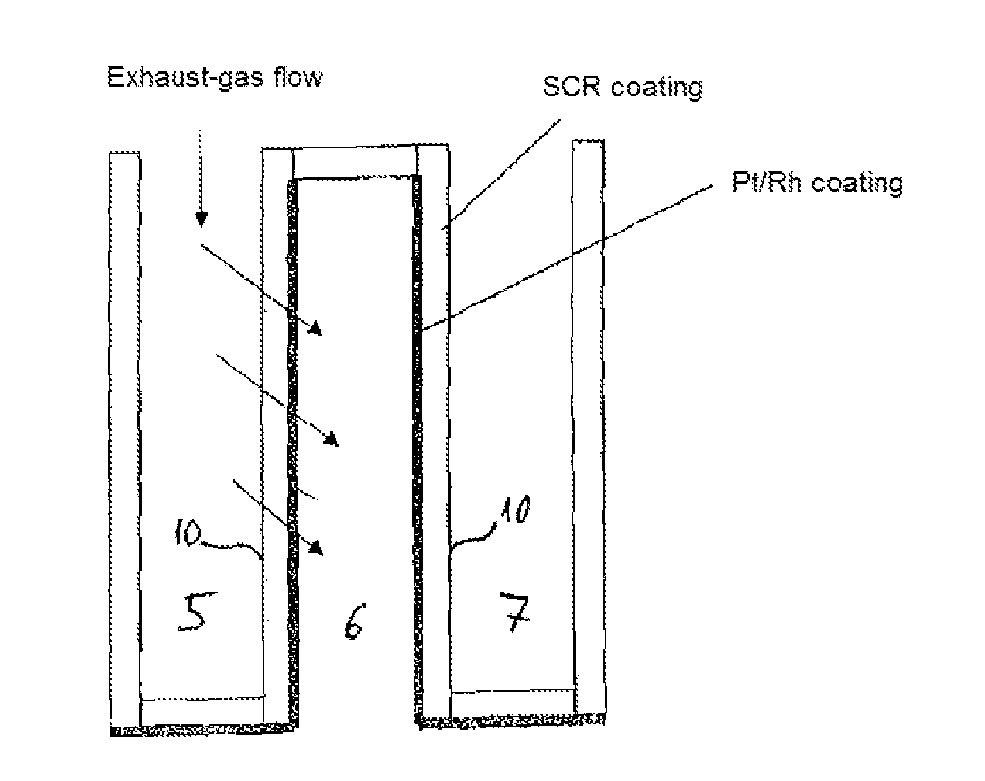
[0071]FIG. 1 shows a schematic representation of a diesel particle filter, designed as wall-flow filter with three adjacent flow ducts 5, 6, 7. A monolithic cordierite support with 600 cpsi and an approximate pore diameter of 10 μm serves as carrier body. Duct 6 is closed in the direction of the exhaust-gas entry side and the ducts 5 and 7 are closed in the direction of the exhaust-gas exit side. The porous carrier body is coated with an ZSM-5 type Fe zeolite on the exhaust-gas entry surface 10 and the inner surface of the porous cordierite monolith. The exhaust-gas exit surface 9 has a Pt / Rh coating which is distributed over the entire exhaust-gas exit surface. The engine-combustion exhaust gas enters the ducts 5 and 7 and, as these are closed at the end, is forced to flow through the cordierite support coated with an SCR active component into the flow duct 6. In the process the SCR reaction takes place. Upon exiting the cordierite support the treated exhaust gas strikes the platin...

example 2

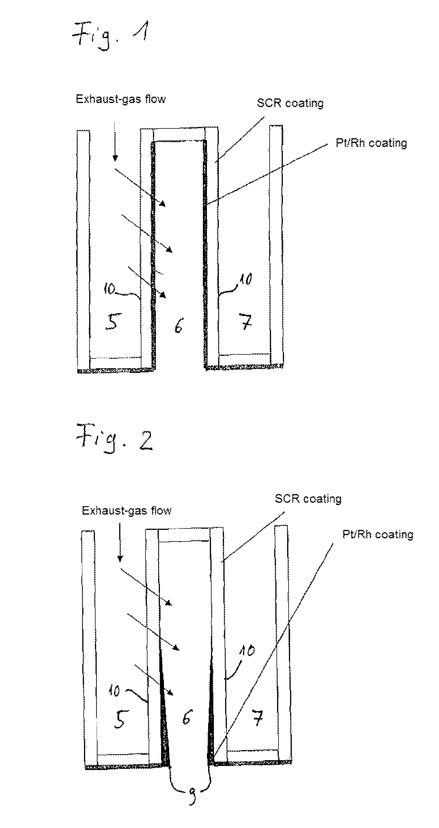
[0074]FIG. 2 shows an analogous particle filter comprising a cordierite monolith with 600 cpsi and a pore diameter of approximately 10 μm. Here, too, the ducts 5 and 7 are closed in the direction of the areas facing the exhaust-gas exit side and the duct 6 closed in the direction of the side facing the exhaust-gas entry side. Here, too, the exhaust gas is forced through the cordierite support coated with an SCR active component (ZSM-5 type Fe zeolite) to flow through the porous wall. The catalytic SCR reaction again takes place there. A Pt / Rh coating, however, present only as partial coating and also with a gradient, is located on the exhaust-gas exit surface 9. In other words, the layer thickness and thus the noble-metal charge increase in the direction of the exhaust-gas exit side. With this catalyst system also, an adequate conversion of NOx to N2 is achieved by the SCR active coating.

[0075]Excess NH3 in normal operation is likewise oxidized to nitrogen by the oxidation catalyst ...


PUM

PropertyMeasurementUnit
temperaturesaaaaaaaaaa

Abstract

The present invention relates to a particle filter comprising a porous carrier body, an SCR active component and an oxidation catalyst, wherein the SCR active component is present as coating on the exhaust-gas entry surface and the inner surface of the porous carrier body and the oxidation catalyst as coating on the exhaust-gas exit surface of the porous carrier body. According to the invention the oxidation catalyst changes its function depending on operating conditions. In normal operation it serves as NH3 slip catalyst for oxidizing excess NH3 and during filter regeneration it operates according to the 3-way principle for converting NOx and CO. The invention also relates to a method for producing the particle filter, the use of the particle filter for treating exhaust gases from the combustion of fossil, synthetic or biofuels as well as an exhaust-gas cleaning system which contains the particle filter according to the invention.

Description

CROSS REFERENCE TO RELATED APPLICATIONS[0001]This application is a national phase of PCT / EP2009 / 007906, filed on Nov. 4, 2009, which claims priority to DE 10 2008 055 890.7, filed Nov. 5, 2008, the entire contents of all are hereby incorporated by reference.[0002]The present invention relates to a particle filter comprising a porous carrier body, an SCR active component and an oxidation catalyst, wherein the SCR active component is present as coating on the exhaust-gas entry surface and the inner surface of the porous carrier body and the oxidation catalyst as coating on the exhaust-gas exit surface of the porous carrier body. The invention also relates to a method for producing the particle filter, the use of the particle filter for treating exhaust gases from the combustion of fossil, synthetic or biofuels as well as an exhaust-gas cleaning system which contains the particle filter according to the invention.BACKGROUND OF THE INVENTION[0003]An exhaust-gas system for diesel combust...

Claims


Application Information

Patent Timeline
Patent Type & Authority Patents(United States)
IPC IPC(8): B01J35/04C01B35/00F01N3/20B01D50/00B01J29/46C01B33/00C01B25/00B01J23/46C01B31/00B01J37/02C01G28/00B01J8/02B01J29/072F01N3/035B01D53/56B01J23/44C01B21/00C01G30/00C01B23/00B01J35/10B01J23/40B01J23/42B01D53/34B01D53/94B01J23/96F01N3/10B01J35/00
CPCB01D2255/9155B01J35/1076B01D2255/1021B01J29/072F01N3/035B01D2255/504B01D53/9468B01D2325/10B01J35/04B01D53/9418B01J23/42B01J23/464B01D2258/012F01N3/2066B01J23/96B01J29/46B01J23/44F01N2250/02B01J37/024B01J37/0246Y02T10/24F01N2510/0682Y10S502/52724Y10S502/52719B01D53/944B01D2251/2067B01J35/002F01N3/103B01D2255/1025B01D2255/20738B01J23/40Y02T10/12
Inventor PAULUS, MARTINWANNINGER, KLAUS
Owner SUED CHEM IP GMBH & CO KG
Why Eureka
Try Eureka