

Torque detecting device and electromotive power steering apparatus mounting the torque detecting device thereon
- Summary
- Abstract
- Description
- Claims
- Application Information
AI Technical Summary
Benefits of technology
Problems solved by technology
Method used
Image

Examples
first embodiment
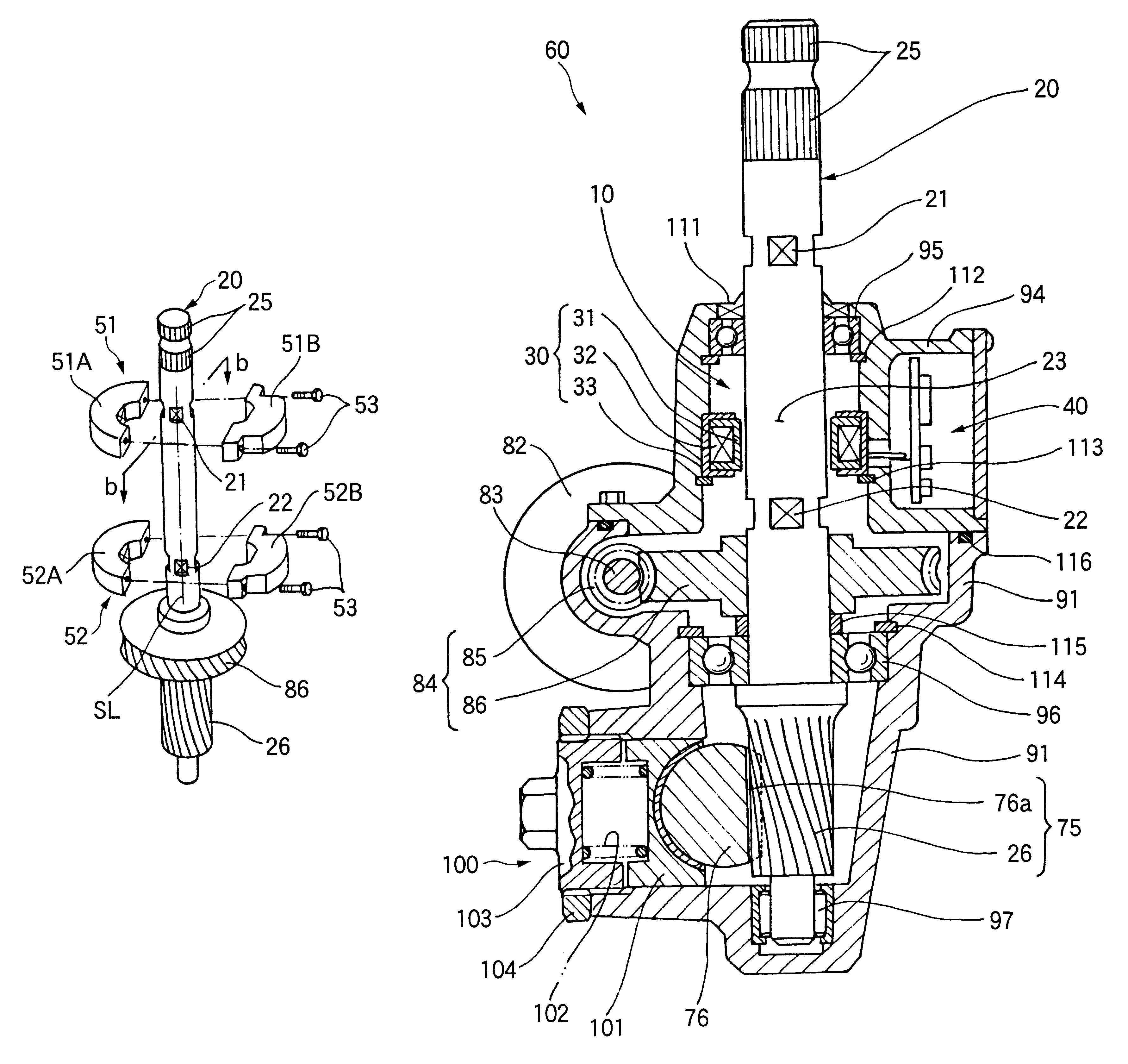
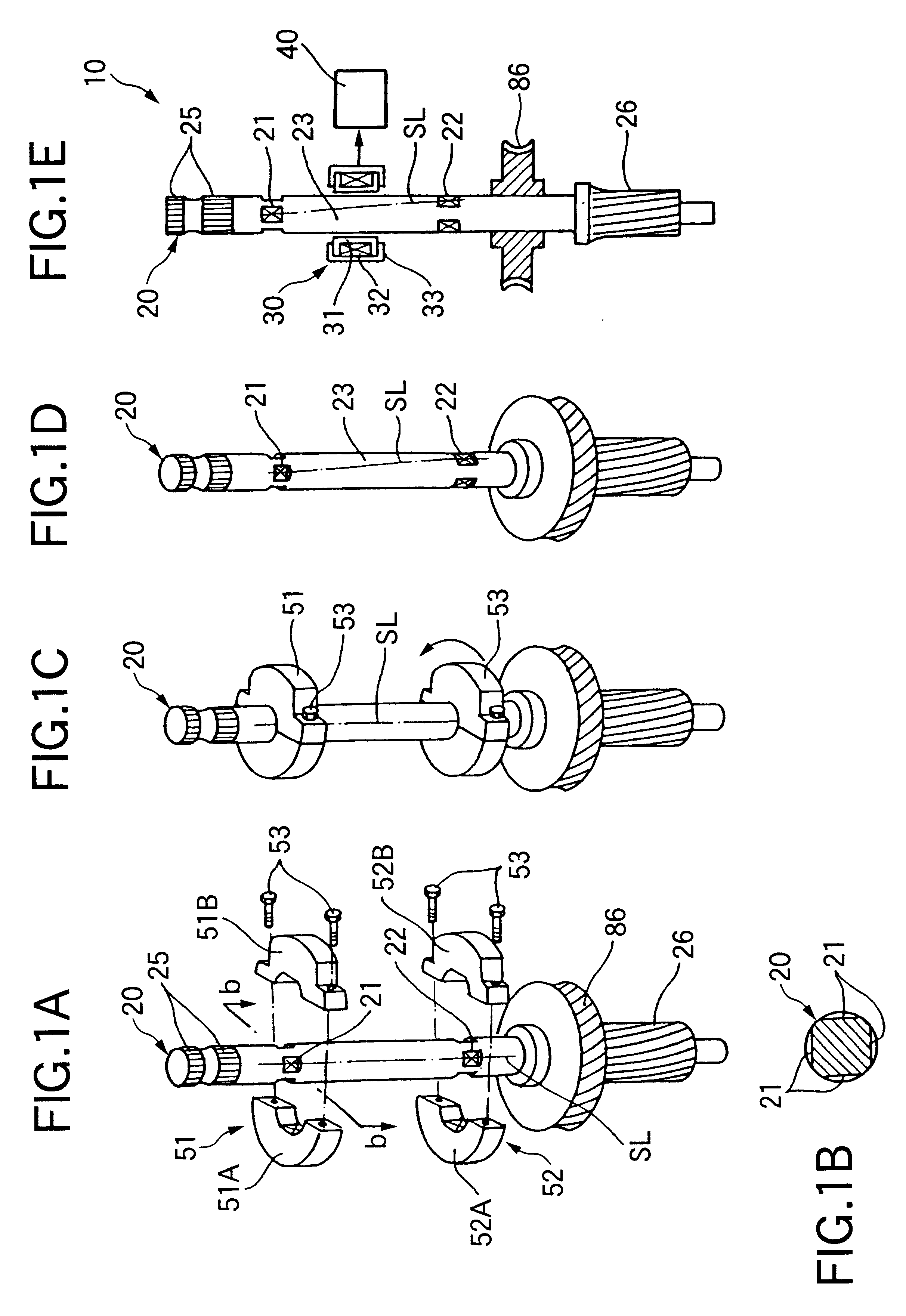
First of all, a torque detecting device and an electromotive power steering apparatus mounting the torque detecting device thereon will be described with reference to FIGS. 1A to 6.
FIGS. 1A to 1E are views illustrating a structure of the torque detecting device according to the first embodiment of the invention and a procedure for manufacturing the torque detecting device.
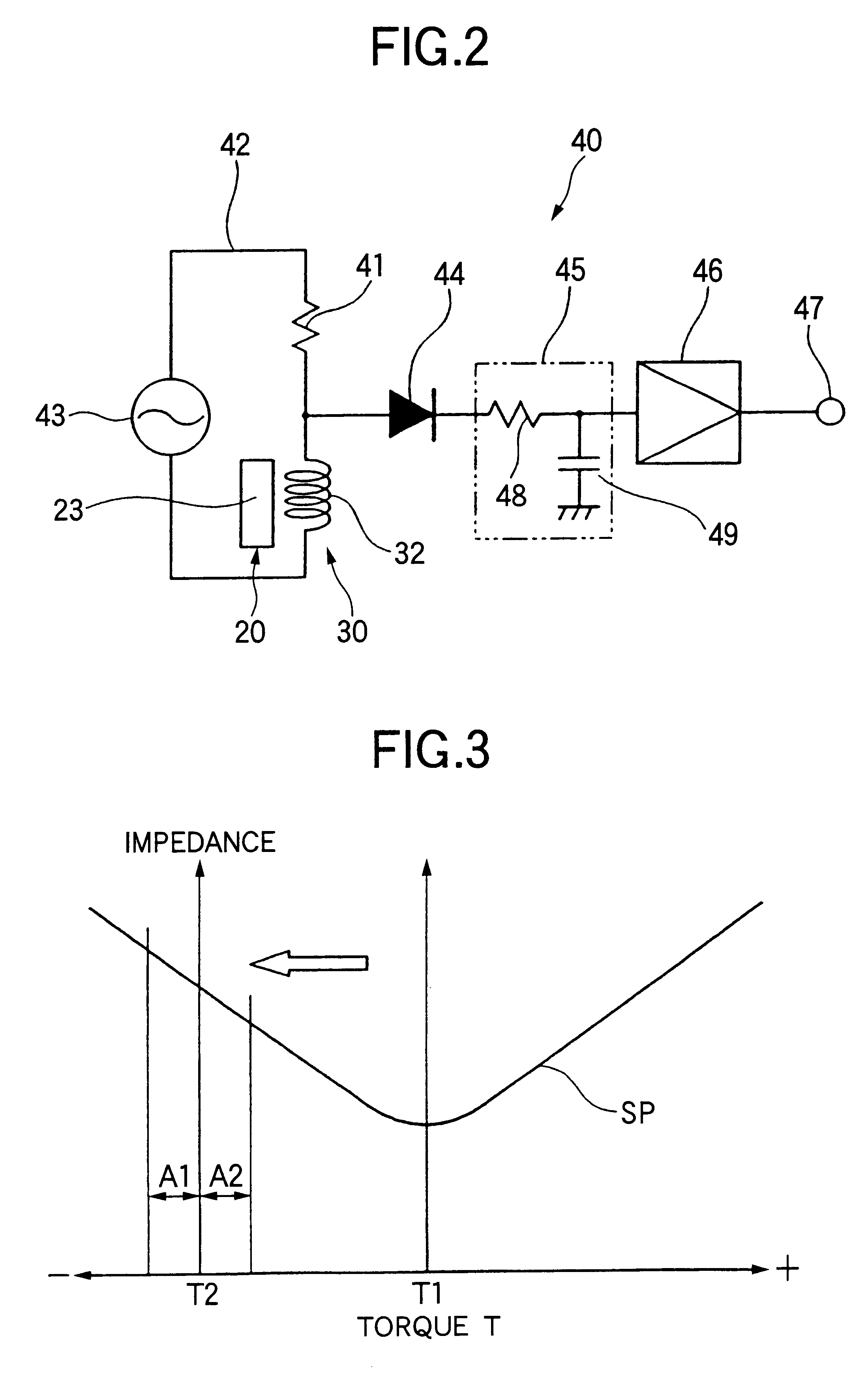
A torque detecting device 10 according to the first embodiment shown in FIG. 1E is a magnetostriction type torque sensor. A permanent strain portion 23 to which a permanent strain is applied for changing a magnetostrictive characteristic corresponding to an applied torque is disposed on a cylindrical rotating shaft 20. A detecting portion 30 for electrically detecting a magnetostrictive effect produced in the permanent strain portion 23 is disposed around the permanent strain portion 23. The detection signal of the detecting portion 30 is processed by an output circuit portion 40 to output a torque detection signa...
second embodiment
FIGS. 7A to 7F are views illustrating the structure of a torque detecting device according to the invention and a procedure for manufacturing the torque detecting device.
A torque detecting device 200 according to the second embodiment shown in FIG. 7F is a magnetostriction type torque sensor. A magnetostrictive film 201 is provided on the surface of a rotating shaft 20 with a predetermined width W over a whole periphery. A detecting portion 30 for electrically detecting a magnetostrictive effect produced in the magnetostrictive film 201 is provided around the magnetostrictive film 201. An output circuit portion 40 processes the detection signal of the detecting portion 30 and outputs it as a torque detection signal.
The magnetostrictive film 201 comprises a plated layer having a predetermined thickness provided between a pair of fixed portions 21 and 22. The plated layer is a film in which a magnetostrictive characteristic is changed according to an applied torque and is characterize...
third embodiment
FIG. 9 is a longitudinal sectional view showing an electromotive power steering apparatus according to the invention corresponding to FIG. 6.
A torque detecting device 300 and an electromotive power steering apparatus 360 mounting the torque detecting device 300 thereon according to the third embodiment are characterized in that (1) a pair of fixed portions 21 and 22 are not provided, (2) a spline coupling portion 25 or a serration coupling portion 25 of a rotating shaft 20 is also used for the fixed portion 21, and (3) a pinion 26 of the rotating shaft 20 is also used for the fixed portion 22 as compared with the torque detecting device 10 and the electromotive power steering apparatus 60 according to the first embodiment shown in FIGS. 1 to 6.
As described above, the rotating shaft 20 is substantially coupled integrally with a worm wheel 86 in an axially longitudinal center portion thereof. As a result, a rigidity is very great in the portion of the rotating shaft 20 to which the wo...
PUM
 Abstract
Description
Claims
Application Information